
Manual

16
D
GB
F
E
96020-02.2015-DGbFEI
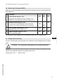
5| Electrical connection
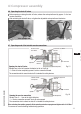
Temperature monitoring connections:
Motor winding: Terminals 1 - 2
Thermal protection thermostat: Terminals 3 - 4
Restart prevention: Terminals 5 - 6
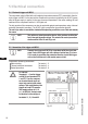
5.4 Electronic trigger unit MP10
Thecompressormotoristtedwithcoldconductortemperaturesensors(PTC)connectedtotheelec-
tronic trigger unit MP10 in the terminal box. Readiness to operate is signalled by the H3 LED (green)
after the power supply is applied. In the case of excess temperature in the motor winding, the unit
switches off the compressor and the H1 LED lights red.
The hot gas side of the compressor can also be protected against overtemperature using a thermal
protection thermostat (accessory). The H2 LED (red) is provided for the protection function.
The unit trips when an overload or inadmissible operating conditions occur. Find and remedy
the cause.
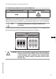
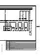
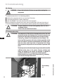
5.5 Connection of the trigger unit MP10
Fig. 18
Terminal board
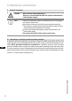
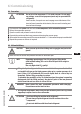
ATTENTION
Terminals 1 - 6 on the trigger
unit MP10 and terminals PTC
1 and PTC 2 on the compres-
sor terminal board must not
come into contact with mains
voltage. This would destroy the
trigger unit and PTC sensors.
The supply voltage at L1-N
(+/-forDC24Vversion)must
be identical to the voltage at
terminals11,12,14and43.
INFO
Theunithasarestartpreventiondevice.Afteryouhaverectiedthe
fault,interruptthemainsvoltage.Thisunlockstherestartprevention
device and the LEDs H1 and H2 go out.
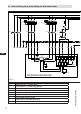
INFO Connect the trigger unit MP10 in accordance with the circuit dia-
gram.Protectthetriggerunitwithadelayed-actionfuse(F)ofmax.
4A.Inordertoguaranteetheprotectionfunction,installthetrigger
unitastherstelementinthecontrolpowercircuit.