
Manual

D
GB
F
E
17
96020-02.2015-DGbFEI
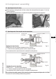
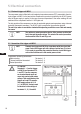
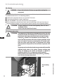
5.7 Oilsumpheater(accessories)
Inordertoavoiddamagetothecompressor,thecompressormustbeequippedwithanoilsump
heater.
Connexion:The oil sump heater must be connected via an auxiliary contact (or parallel wired auxiliary
contact) of the compressor contactor to a seperate electric circuit.
Electrical data: 230 V - 1 - 50/60 Hz, 80 W.
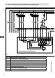
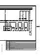
5| Electrical connection
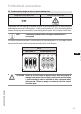
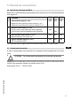
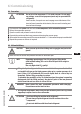
The compressor and the trigger unit MP10 are operational when the H3 LED (green) lights.
5.6 Function test of the trigger unit MP10
Pos
Procedure
LED H1 LED H2 LED H3
red red green
1
•Interruptpowersupply(L1orS1) OFF OFF OFF
• Release the motor temperature sensor connection (1 or 2)
• Release the hot gas temperature sensor (if installed) (3 or 4)
2
•Restorethepowersupply(L1orS1) ON
• Function check of motor temperature sensor: operational ON
• Function check of hot gas temperature sensor: operational ON
3
•Interruptpowersupplyagain(L1orS1) OFF OFF OFF
• Reconnect terminals 1 or 2 and/or 3 or 4
4
•Restorethepowersupply(L1orS1): OFF OFF ON
• MP10 is operational again
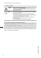
Before start-up, troubleshooting or making changes to the control power circuit, check the functionality
of the trigger unit:
ATTENTION The oil sump heater must generally be connected and operated.