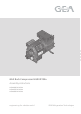
D 6 7 8 9 10 11 12 13 1 2 3 4 GB 5 F E GEA Bock Compressor HGX4 R134a 96179-01.
About these instructions Read these instructions before assembly and before using the compressor. This will avoid misunderstandings and prevent damage. Improper assembly and use of the compressor can result in serious or fatal injury. Observe the safety instructions contained in these instructions. These instructions must be passed onto the end customer along with the unit in which the compressor is installed.
96179-01.2015-DGbFEI Contents 1 1.1 1.2 1.3 1.4 2 2.1 2.2 2.3 3 3.1 3.2 3.3 4 4.1 4.2 4.3 4.4 4.5 4.6 4.7 5 5.1 5.2 5.3 5.4 5.5 5.6 5.7 5.8 5.9 6 6.1 6.2 6.3 6.4 6.5 6.6 6.7 6.8 7 7.1 7.2 7.3 7.4 7.5 7.
1| Safety 1.1 Identification of safety instructions: DANGER! Indicates a dangerous situation which, if not avoided, will cause immediate fatal or serious injury. WARNING! Indicates a dangerous situation which, if not avoided, may cause fatal or serious injury. CAUTION! Indicates a dangerous situation which, if not avoided, may cause fairly severe or minor injury. ATTENTION! Indicates a situation which, if not avoided, may cause property damage.
1| Safety 1.4 Intended use These assembly instructions describe the standard version of the HGX4 R134a manufactured by GEA Bock. The compressor is intended for use in refrigeration systems in compliance with the limits of application. Only the refrigerant specified in these instructions may be used.
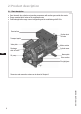
2| Product description 2.1 Short description • Semi-hermetic four-cylinder reciprocating compressor with suction-gas cooled drive motor. • Flange-mounted drive motor on the compressor case. • Preferred application range: normal refrigerating and air-conditioning with R134a. Terminal box Suction shutoff valve Transport eyelet Valve plate Motor section Cylinder cover Discharge shut-off valve D GB Oil pump F 6 7 8 9 10 11 12 13 1 2 3 4 Name plate 5 Drive section E Oil sight glass Fig.
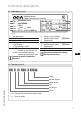
2| Product description 2.2 Name plate (example) GEA Bock GmbH 72636 Frickenhausen, Germany 1 2 3 4 5 HGX4/650-4 R134a AS35830A006 22,0 A 84 A 109 A 6 7 8 9 10 11 12 13 56,6 67,9 SE 55 Fig. 2 1 2 3 4 5 Type designation Machine number maximum operating current Starting current (rotor blocked) Y: Part winding 1 YY: Part windings 1 and 2 ND (LP): max. admissible operating pressure (g) Low pressure side HD (HP): max.
3| Areas of application 3.1 Refrigerants • HFKW / HFC: R134a 3.2 Oil charge The compressors are filled at the factory with the following oil type: FUCHS Reniso Triton SE 55 Compressors with ester oil charge (FUCHS Reniso Triton SE 55) are marked with an X in the type designation (e.g. HGX4/650-4 R134a). INFO! ATTENTION! D For refilling, we recommend the above oil types. Alternatives: see lubricants table, Chapter 7.5.
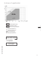
3| Areas of application R134a Fig. 4 Unlimited application range D Supplementary cooling or reduced suction gas temperature GB Evaporation temperature (°C) F Condensing temperature (°C) E Suction gas superheat (K) Suction gas temperature (°C) Max. permissible operating pressure (LP/HP)1): 19/28 bar 1) LP = low pressure HP = high pressure 96179-01.
4| Compressor assembly INFO! New compressors are factory-filled with inert gas (3 bar nitrogen). Leave this service charge in the compressor for as long as possible and prevent the ingress of air. Check the compressor for transport damage before starting any work. 4.1 Storage and transport Fig. 5 ? Storage at (-30°C) - (+70°C), maximum permissible relative humidity 10% - 95%, no condensation Do not store in a corrosive, dusty, vaporous atmosphere or in a combustible environment. Use transport eyelet.
4| Compressor assembly T he pipe connections have graduated inside diameters so that pipes with standart millimetre and inch dimensions can be used. The connection diameters of the shut-off valves are rated for maximum compressor output. The actual required pipe cross section must be matched to the output. The same applies for non-return valves. Fig. 10: graduated internal diameter 4.4 Pipes Pipes and system components must be clean and dry inside and free of scale, swarf and layers of rust and phosphate.
4| Compressor assembly 4.6 Operating the shut-off valves Before opening or closing the shut-off valve, release the valve spindle seal by approx. ¼ of a turn counter-clockwise. After activating the shut-off valve, re-tighten the adjustable valve spindle seal clockwise. Release Tighten Valve spindle seal Fig. 12 Fig. 13 4.
5| Electrical connection 5 Electrical connection DANGER! High voltage! Risk of electric shock! Only carry out work when the electrical system is disconnected from the power supply! INFO! onnect the compressor motor in accordance with the circuit diagram C (see inside of terminal box). Use suitable cable entry point of the correct protection type (see name plate) for routing cables into the terminal box. Insert the strain reliefs and prevent chafe marks on the cables.
5.3 Basic circuit diagram for part winding start with standard motor 1 0 2 F1.1 F1.2 I=66% I=33% 3 4 F2 4A S1 Q1 1 3 5 2 4 6 K1 1 3 5 2 4 6 K2 F1.1 F1.2 XSS L1 L2 L3 N PE 1 2 3 PE 4 5 6 7 8 9 10 11 D GB M1 F 1U1 E 1V1 1W1 M Y/YY 2U1 2V1 X1 L1 L1 N L N 43 43 11 X2 1 4 S 12 M 14 2W1 R1 2 3 5 6 MP10 R2 AnschluákastenVerdichter Compressor terminal box Fig.
5 6 7 8 9 L1.1 L2.1 L3.1 L1.2 K1 K1 K1 K1T K1 12 13 14 15 16 17 18 K2 19 20 K1T 21 22 N PE 23 24 25 26 D F5 GB T2 N L M S P> P F3 F4 P< F B1 E P™l 96179-01.2015-DGbFEI E1 PWMP10 Q1 M1 K1 K2 K1T S1 E1 Main switch Compressor motor Mains contactor (part winding 1) Mains contactor (part winding 2) Delay relay max. 1s Control voltage switch Oil sump heater = + BOCKCOMPRESSORS 1 Bl. 1 Bl.
5| Electrical connection The motor is wired for direct start (YY) at the factory. For part winding start Y / YY, the bridges must be removed and the motor feed line connected according to the circuit diagram: 400 V Direct start YY YY Direktstart Part winding start Y/YY Teilwicklungsstart Y/YY L1 L2 L3 2U1 2V1 2W1 2U1 2V1 2W1 1U1 1V1 1W1 1U1 1V1 1W1 L1 L2 L3 L1 L2 L3 ATTENTION! F ailure to do this results in opposed rotary fields and results in damage to the motor.
5| Electrical connection 5.4Sondermotor: Sondermotor:Ausführung Ausführungfür fürDirektDirekt-oder oderStern-Dreieck-Anlauf Stern-Dreieck-Anlauf 5.4 5.4 Special motor: design for direct or star-delta Fürden denStern-Dreieck-Anlauf Stern-Dreieck-Anlaufist isteine einemechanische mechanischestart Anlaufentlastungmit mitBypass-Magnetventil Bypass-Magnetventil Für Anlaufentlastung (Zubehör) erforderlich.
5.5 Basic circuit diagram for star-delta start with special motor 1 0 2 3 4 F2 4A F1.1 S1 F1.1 Q1 1 3 5 2 4 6 1 2 3 K1 1 3 5 2 4 6 K3 Y 1 3 5 2 4 6 4 5 6 K2 D F1.2 F1.2 D GB XSS L1 L2 L3 N PE PE 7 8 9 10 11 F E U1 V1 M1 M 3 ~ W1 W2 U2 X1 L1 L1 N L N 43 43 11 X2 1 4 S 12 M 14 V2 R1 2 3 5 6 MP10 R2 AnschluákastenVerdichter Compressor terminal box Fig.
5 6 7 9 8 L1.1 L2.1 L3.1 L1.2 K1 K1 K1 12 13 14 15 16 T2 N L M S K3 K4T K4T K3 K2 K2 K1 K5T K3 17 K4T 18 AL 19 20 K5T 21 22 N PE 23 24 25 D GB 26 F F5 P> P F3 F4 E P< B1 P™l 96179-01.
5| Electrical connection 5.6 Electronic trigger unit MP 10 The compressor motor is fitted with cold conductor temperature sensors (PTC) connected to the electronic trigger unit MP 10 in the terminal box. Readiness to operate is signalled by the H3 LED (green) after the power supply is applied. In the case of excess temperature in the motor winding, the unit switches off the compressor and the H1 LED lights red.
5| Electrical connection 5.
5| Electrical connection 5.9 Oil sump heater (accessories) During compressor standstill and depending on the pressure and ambient temperature, r efrigerant diffuses into the compressor's lubricating oil. This reduces the oil's lubricating ability. When the compressor is started, the refrigerant contained in the oil evaporates due to the decline in pressure. This can result in oil foaming and oil exodus which can result in oil hammer in certain circumstances.
6| Commissioning 6.1 Preparations for start-up INFO! In order to protect the compressor against inadmissible operating conditions, high-pressure and low-pressure pressostats controls are mandatory on the installation side. The compressor has undergone trials in the factory and all functions have been tested. There are therefore no special running-in instructions. Check the compressor for transport damage! 6.
6| Commissioning 6.5 Refrigerant charge CAUTION! Wear personal protective clothing such as goggles and protective gloves! Make sure that the suction and pressure line shut-off valves are open. With the compressor switched off, add the liquid refrigerant directly to the condenser or receiver, breaking the vacuum.
6| Commissioning 6.8 Connection of oil level regulator 12 4o 124 o o 4 12 Oil level regulation systems have proven themselves with parallel circuits of several compressors. The connection "0" is provided for installing an oil level regulator (see dimensions drawing). All common oil level regulators from AC&R, ESK and Carly as well as the OM3 TraxOil oil level regulation system from Alco can be connected directly without adapters (see Fig. 18). A sight glass on the oil level regulator is not required.
7| Maintenance 7.3 Spare part recommendation HGX4 / ...R134a 555-4 650-4 465-4 Ref. No. Designation Set of gaskets Ref. No. 08913 Valve plate kit 08247 Oil pump kit Oil sump heater kit 230 V ~ Only use genuine GEA Bock spare parts! 08248 08384 08425 7.4 Accessories Available accessories can be found on the Internet at www.gea.com 7.5 Extract from the lubricants table D The oil type filled as standard in the factory is marked on the name plate . This oil type should be used as a preference.
56,6 / 67,9 1 Voltage 380-420 V Y/YY - 3 - 50 Hz PW 440-480 V Y/YY - 3 - 60 Hz PW PW = Part Winding Winding ratio: 66% / 33% kW A 22 19 16 13,1 11,2 9,4 2 PW 1 + 2 2 Max. power consumption Max. Operating current Electrical data 3 1 Tolerance (± 10%) relative to the mean value of the voltage range. Other voltages and types of current on request. 2 - The specifications for max. power consumption apply for 50Hz operation.
Q 73 112 436 550 (535) ca.725 (690) ca.245 Fca.725 (690) 436 550 (535) ca.725 (690) Maße in mm Dimensions in mm Cotes en mm Änderungen vorbehalten Subject to change without notice Sous réserve de toutes modifications D 4xP F J Maße Zub E H C D1 EO HK D1 O 11 ÖV 280 330 K Anschlüsse SV Saugabsperrventil, Rohr ca.455 C B1 X ÖV (L)* Suction line valve, tube C E H D O Ansicht X: A View X: Pos Vue X : Rac X Connections 330 ca.680ca.680 B Schwingungsdämpfer 280 330 Maße Z B1 ca.
9| Dimensions and connections SV DV Suction line Discharge line A Connection suction side, not lockable A1 Connection suction side, lockable B Connection discharge side, not lockable B1 Connection discharge side, lockable C Connectoin oil pressure switch OIL D Connection oil pressure switch LP D1 Connection oil return from oil separator E Connection oil pressure gauge 1/ “ NPTF 8 7/ “ UNF 16 1/ “ NPTF 8 7/ “ UNF 16 7/ “ UNF 16 7/ “ UNF 16 1/ “ NPTF 4 7/ “ UNF 16 F Oil drain M 22 x 1,5
10| Declaration of conformity and installation DECLARATION OF CONFORMITY CE 96 for using the compressors within the European Union (in accordance with Low Voltage Directive 2006/95/EC) We hereby declare that the following refrigerating compressors Product designation: HGX4 R134a comply with the Low Voltage Directive 2006/95/EC.
11| Service Dear customer, GEA Bock compressors are top-quality, reliable and service-friendly quality products. If you have any questions about installation, operation and accessories, please contact our technical service or specialist wholesaler and/or our representative. The GEA Bock service team can be contacted by phone with a toll-free hotline 00 800 / 800 000 88 or via e-mail: refrigeration@gea.com Yours faithfully GEA Bock GmbH Benzstraße 7 72636 Frickenhausen Germany D GB F 96179-01.
We live our values. Excellence • Passion • Integrity • Responsibility • GEA-versity D GEA Group is a global engineering company with multi-billion euro sales and operations in more than 50 countries. Founded in 1881, the company is one of the largest providers of innovative equipment and process technology. GEA Group is listed in the STOXX® Europe 600 index. GB F GEA Bock GmbH Benzstraße 7, 72636 Frickenhausen, Germany Telephone: +49 7022 9454-0, Fax: +49 7022 9454-137 refrigeration@gea.com, www.gea.