
Manual

18
D
GB
F
E
96179-01.2015-DGbFEI
nderung
0
Datum Name
Datum
Bearb.
Gepr.
Norm
1
20.Feb.2009
Kelich
09.M„r.2010
Urspr.
2
Ers.f.
3
Ers.d.
4
D/S
MP10
5 6 7
BOCKCOMPRESSORS
8
=
+
9
Bl.
1
Bl.
1
XSS
Q1
L1 L2 L3 N PE
F1.1
K1
1
2
F1.2
1
AnschluákastenVerdichter
3
4
2
5
6
3 PE
U1
V1
W1
M
3
~
M1
Y
K3
1
2
3
4
R1
5
6
W2
U2
V2
D
K2
1
2
4
3
4
5
5
6
6
X1 L1 L1 N N 43 4311 12 14
LSM
X2123456
7
F1.1
F1.2
8
R2
4A
F2
S1
9 10
MP10
11
F5
K1
12
T2
13
N
P™l
14
L
15
M
16
S
K1
K1
K3
P>
F3
K4T
K3
K2
17
K4T
K2
K3
18 19
K4T
P
F4
20
K5T
AL
21 22
K5T
P<
B1
23 24
K1
25
E1
26
L1.1
L2.1
L3.1
L1.2
N
PE
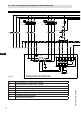
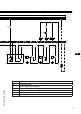
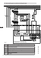
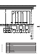
5.5 Basic circuit diagram for star-delta start with special motor
Fig. 17
R1 Cold conductor (PTC sensor) motor winding
R2 Thermal protection thermostat (PTC sensor)
F1.1 /1.2
2 motor protection switches
F2 Control power circuit fuse
F3 High pressure safety monitor
F4 Safety chain (high/low pressure monitoring)
F5 Oil differential pressure monitor
B1 Enabling switch (thermostat)
Q1 Main switch
Compressor terminal box