GEAR HEAD GAP BED LATHE 65044 Model 66164 Set up and Operating Instructions Unless noted otherwise, SKU 66164 - 13” x 40” Lathe - shown throughout this manual. Visit our website at: http://www.harborfreight.com Read this material before using this product. Failure to do so can result in serious injury. Save this manual. Copyright© 2008 by Harbor Freight Tools®. All rights reserved.
Contents Important SAFETY Information ���������������������������� 3 General Tool Safety Warnings �������������������������������������� 3 Lathe Safety Warnings ������������ 5 Grounding Instructions ����� 6 PARTS LIST C - APRON ������������������ 23 ASSEMBLY DIAGRAM C - APRON � 24 PARTS LIST AND ASSEMBLY DIAGRAM D - BED ������������������������ 25 PARTS LIST AND ASSEMBLY DIAGRAM E - BED & DRIVE �������� 26 PARTS LIST F - SADDLE ���������������� 27 ASSEMBLY DIAGRAM F - SADDLE 28 125 V~ Rewiring ����������
NOTICE is used to address practices not related to personal injury. Save This Manual Keep this manual for the safety warnings and precautions, assembly, operating, inspection, maintenance and cleaning procedures. Write the product’s serial number in the back of the manual near the assembly diagram (or month and year of purchase if product has no number). Keep this manual and the receipt in a safe and dry place for future reference.
7. 8. DON’T FORCE TOOL. It will do the job better and safer at the rate for which it was designed. USE RIGHT TOOL. Don’t force tool or attachment to do a job for which it was not designed. RECOMMENDED MINIMUM WIRE GAUGE FOR EXTENSION CORDS (240 VOLT) NAMEPLATE AMPERES (at full load) EXTENSION CORD LENGTH 50’ 100’ 200’ 300’ 0–6 18 16 16 14 6.1 – 10 18 16 14 12 10.1 – 12 16 16 14 12 12.1 – 16 14 12 Do not use. TABLE A 9. USE PROPER EXTENSION CORD.
or other part that is damaged should be properly repaired or replaced. 20. DIRECTION OF FEED. Feed work into a blade or cutter against the direction of rotation of the blade or cutter only. 21. NEVER LEAVE TOOL RUNNING UNATTENDED. TURN POWER OFF. Don’t leave tool until it comes to a complete stop. Lathe Safety Warnings For Your Own Safety Read Instruction Manual Before Operating Lathe 1. Wear eye protection. 2. Do not wear gloves, necktie, or loose clothing. 3. Tighten all locks before operating.
particles. (California Health & Safety Code § 25249.5, et seq.) 12. WARNING: Handling the cord on this product will expose you to lead, a chemical known to the State of California to cause cancer, and birth defects or other reproductive harm. Wash hands after handling. (California Health & Safety Code § 25249.5, et seq.) 13. The warnings, precautions, and instructions discussed in this instruction manual cannot cover all possible conditions and situations that may occur.
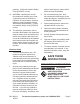
2. 1. This tool is intended for use on a circuit that has an outlet that looks like the one illustrated above in 250 V~ 3-Prong Plug and Outlet. The tool has a grounding plug that looks like the plug illustrated above in 250 V~ 3-Prong Plug and Outlet. Make sure the tool is connected to an outlet having the same configuration as the plug. No adapter is available or should be used with this tool.
Specifications Model 65044 Electrical Requirements Fuses Lathe Type Motor Speed Spindle Speeds Spindle Taper Spindle Bore Drive Method V-Belt Markings Swing Over Bed Swing Over Gap Center to Center Tool Slide Travel Tailstock Quill Travel Tailstock Quill Taper Threading Capacity Tool Post Capacity Tool Post Style Mounting Holes 66164 ACCESSORIES 66164 110/220 V~ ; 60 Hz ; 17/8.
HOISTING & INSTALLATION Read the entire Important Safety Information section at the beginning of this manual including all text under subheadings therein before set up or use of this product. 5. Raise the Lathe slightly up from the floor surface, making sure the Lathe is properly balanced. Then remove the six Screws (5D), Washers (9D), and Nuts (10D) which secure the Lathe to its Chip Pan (8D). 6. Set the Chip Pan upon the stand.
direction of either the longitudinal or cross feeds. PRODUCT FEATURES & OPERATING GUIDE Note: Refer to Figure C for control locations. 3. Starting Handle (11I): The Starting Handle Locks in the center location; move it to the right to unlock it. For a clockwise rotation, move the Spindle Handle down. For a counterclockwise rotation, move the Spindle Handle up. With the Handle in the middle position, the Spindle will not rotate. 4.
7. Hand Wheel (2C): The Hand Wheel is used to manually move the Apron Case (65C) along the Lathe Bed (1D). 8. Thread Lever (45C): The Thread Lever is used to engage the Half Nuts (56C, 57C) when threading. 9. Cross Feed Crank (28F): The Cross Feed Crank is used to manually move the Slide Plate (18F) in or out. 10. Compound Slide Crank (17G): The Compound Slide Crank is used to manually move the Tool Post (35G).
a. Open the Gear Box Cover (120A), and using a suitable wrench, hold the Arbor Shaft to prevent it from turning. Grip the Chuck or Faceplate, and rotate it in a counterclockwise direction to unthread it from the Arbor Shaft. b. When re-installing a Chuck or Faceplate, be sure to put light grease on the threaded end of the Arbor Shaft to ease installation and removal of the Chuck or Faceplate. c. You are provided with a 3-Jaw Chuck (118A) and a 4-Jaw Chuck (119A).
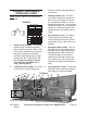
FIGURE E 66164 Exclusive Controls Feed Gear Levers (115A) and (116A): To change either of the Feed Gear Levers (115A, 116A), you must first unlock the Thread/Feed Selector (117A). These Feed Gear Levers are for selecting threading or feed. Feed Gear Lever (115A) features four positions. “G” and “E” positions are to adjust the Feeding Rod. “F” and “D” are to adjust the Lead Screw. Feed Gear Lever (116A) features eight positions.
65044 Exclusive Controls CAUTION: To prevent damage: Stop the spindle before adjusting the controls. Thread/Feed Selector Feed Rate Levers 1. Use Thread/Feed Selector to select threading or feeding. Position the Lead / Feed Lever (100A) to the Left for feeding. Center position is neutral. Right position is for lead screw. 2. Feed Rate Levers, control the feed gear box. The left Lever has five positions which are identified Alphabetically.
STARTING Before starting the Lathe: 1. Check and adjust Drive Belt (121A) tension. See “Maintenance & Service” section. 2. Make sure the lathe is properly lubricated. 3. Make sure the Lathe has sufficient oil. During operation, if the oil level falls below the red line on the oil gauge, immediately stop machining and add oil until the level is at the red line. 4. Make sure all levers and controls are tight and in the proper position. 5. Turn the Emergency Switch (112A) clockwise.
press the Drive Belt approximately 1/2 inch. If the Belt is too tight, it will wear the Bearings. If it is too loose, it will slip on the Pulleys and wear out prematurely. Maintenance And Service Procedures not specifically explained in this manual must be performed only by a qualified technician.
lubricating oil (30 weight) through the Oil Fill Cap until the oil level is at the red line on the Oil Gauge. Dispose of waste oil properly, and in accordance with local regulations. If during operation the oil is below the red line, immediately stop machining and add oil until the level is at the red line. (See Figure G.) 4. After Use, clean external surfaces of the tool with a clean cloth.
TROUBLESHOOTING Problem Quality of cut is poor. Possible Cause 1. Cutting tool is above workpiece center line. 2. Lathe speed too slow. 3. Cutting tool is dull. 4. Cutting too aggressively. Excessive vibration when 1. Cutting tool is positioned below turning thin workpieces. workpiece center line. 2. Cutting too aggressively. Excessive vibration when 1. Headstock and/or tailstock turning larger workpieces improperly located at ends of or bowls. workpiece. 2. Workpiece is unbalanced.
Parts Lists and Diagrams PARTS LIST A - HEAD STOCK Note: When ordering parts from the following lists, indicate the part name and part number with the suffix of the lit it is on. (Example: “Screw, Part #1A.”) Part Description Qty. Part Description Qty. 1A Screw (M8 x 25) 4 31A Gear 1 2A Cover 1 32A Gear 1 3A Oil Seal (0.
PARTS LIST A - HEAD STOCK (cont.) Part Description Qty. Part Description Qty. 60A Bearing (104) 1 92A Circlip (#2) 3 61A Screw (M6 x 16) 2 93A Cover 1 62A Oil Seal (0.5mm) 3 94A Screw 1 63A Cover 1 95A Screw (M6 x 25) 6 64A Collar 1 96A Oil Seal (0.5mm) 1 65A Shaft 1 97A Headstock 1 66A Key (5 x 20) 1 98A Shaft 1 67A Gear 1 99A Collar 1 68A Shaft 1 100A Direction Control 1 69A Oil Seal (22 x 2.
Power Switch (111A) not shown. Emergency Stop (112A) not shown. Inching Switch (113A) not shown. Indicator Light (114A) not shown. 3-Jaw Chuck (118A) not shown. 4-Jaw Chuck (119A) not shown. Gear Box Cover (120A) not shown. Drive Belt (121A) not shown. ASSEMBLY DIAGRAM A - HEAD STOCK SKU 65044 66164 For technical questions, please call 1-800-444-3353.
PARTS LIST AND ASSEMBLY DIAGRAM B - CHANGE GEAR Part 1B 2B 3B 4B 5B 6B 7B Description Screw (M6 x 12) Washer Gear Key (5 x 8) Screw (M6 x 12) Washer Gear SKU 65044 66164 Qty. 1 1 1 1 1 1 1 Part 8B 9B 10B 11B 12B 13B Description Bearing (80202) Collar Quadrant Shaft Gear Key (A5 x 23) For technical questions, please call 1-800-444-3353. Qty.
PARTS LIST C - APRON Part Description Qty. Part 35C Screw (M6 x 12) Qty.
ASSEMBLY DIAGRAM C - APRON SKU 65044 66164 For technical questions, please call 1-800-444-3353.
PARTS LIST AND ASSEMBLY DIAGRAM D - BED Part Description Qty. Part 6D Bracket Qty. 1D Lathe Bed 2D Rack Gear 1 7D Screw 2 3D Pin 6 8D Chip Pan 1 4D Screw 6 9D Washer 6 5D Screw 6 10D Nut 6 SKU 65044 66164 1 Description For technical questions, please call 1-800-444-3353.
PARTS LIST AND ASSEMBLY DIAGRAM E - BED & DRIVE Part Description Qty. Part 10E Bracket 1 Description Qty. 1E Cover 2E Screw 2 11E Screw (M8 x 25) 4 3E Nut 2 12E Motor (1.1Kw) 1 4E Nut (M10) 1 13E Nut (M10) 4 5E Screw 1 6E Nut (M12) 2 14E Screw (M10 x 40) 4 7E Plate 1 15E Key (8 x 40) 1 8E Washer (#12) 2 16E Pulley 1 9E Shaft 2 17E Power Cord 1 13-1E Washer (#10) 2 1 Power Cord (17E) not shown.
PARTS LIST F - SADDLE Part Description Qty. Part Description Qty.
ASSEMBLY DIAGRAM F - SADDLE SKU 65044 66164 For technical questions, please call 1-800-444-3353.
PARTS LIST AND ASSEMBLY DIAGRAM G - TOOL POST Part 1G 2G 3G 4G 5G 6G 7G 8G 9G 10G 11G 12G 13G 14G 15G Description Screw Gib Compound Slide Nut (M10) Screw Screw Nut Screw (M6 x 12) Nut (M6) Screw Bearing (8101) Bracket Bearing (8101) Index Ring Nut SKU 65044 66164 Qty.
PARTS LIST AND ASSEMBLY DIAGRAM H - Tailstock Part 1H 2H 3H 4H 5H 6H 7H 8H 9H 10H 11H 12H 13H 14H Description Center Key Quill Tailstock Base Set Screw Screw Pin (4 x 8) Bearing (8101) Bracket Index Ring Screw (M6 x 20) Hand Wheel Handle SKU 65044 66164 Qty.
PARTS LIST AND ASSEMBLY DIAGRAM I - CONTROL SWITCH Part 1I 2I 3I 4I 5I 6I 7I 8I 9I 10I Description Bracket Screw (M10 x 60) Oil Cup Pin (6 x 55) Pin (4 x 30) Collar Rod Key (5 x 38) Pin (4 x 20) Spring SKU 65044 66164 Qty. 1 2 2 2 1 1 1 1 1 1 Part 11I 12I 13I 14I 15I 16I 17I 18I 19I Description Starting Handle Bracket Screw (M6 x 20) Pin (5 x 20) Bracket Circlip (#32) Screw (M8 x 25) Bracket Switch For technical questions, please call 1-800-444-3353. Qty.
(65044 ONLY) PARTS LIST J - 65044 GEARBOX Part Description Qty. Part Description Qty.
(65044 ONLY) ASSEMBLY DIAGRAM J - 65044 GEARBOX SKU 65044 66164 For technical questions, please call 1-800-444-3353.
(66164 ONLY) PARTS LIST K - 66164 GEARBOX Part Description Qty. Part Description Qty.
(66164 ONLY) ASSEMBLY DIAGRAM K - 66164 GEARBOX SKU 65044 66164 For technical questions, please call 1-800-444-3353.
Wiring Diagrams ELECTRIC PANEL CONNECTION CONNECTION BETWEEN ELECTRIC PANEL & OUTSIDE COMPONENTS SKU 65044 66164 For technical questions, please call 1-800-444-3353.
ELECTRICAL SCHEMATIC LIMITED 1 YEAR / 90 DAY WARRANTY Harbor Freight Tools Co. makes every effort to assure that its products meet high quality and durability standards, and warrants to the original purchaser that for a period of ninety days from date of purchase that the engine/motor, the belts (if so equipped), and the blades (if so equipped) are free of defects in materials and workmanship.