
user manual


Page 10SKU 65044
66164
For technical questions, please call 1-800-444-3353.
PRODUCT FEATURES &
OPERATING GUIDE
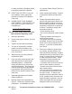
Note: Refer to Figure C for control loca-
tions.
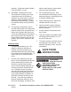
FIGURE B
Spindle Speed Chart
1 2 3
A
60 Hz 270 1400 800
50 Hz 250 1500 850
B
60 Hz 75 360 220
50 Hz 50 325 200
C
60 Hz 200 1000 600
50 Hz 150 950 540
Spindle Speed Chart
60
Hz
I II
1 2 3 1 2 3
A 320 1550 950 220 1150 700
B 90 430 260 60 300 200
C 240 1200 725 180 890 525
A
B
C
1
2
3
89A
1. Shifter Controls (89A): The Spindle
speed can be controlled by setting
the two Shifter Controls. Refer to the
Chart on the Headstock to determine
the proper setting for the desired
Spindle rotation speed (18 or 9 step
speeds from 60 to 1550 RPM). Do
not change the settings of these
controls when the Motor is run-
ning. (See Figure B.)
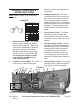
Lead/Feed Lever (100A):2. The Lead/
Feed Lever is used to change the
direction of either the longitudinal or
cross feeds.
Starting Handle (11I):3. The Start-
ing Handle Locks in the center loca-
tion; move it to the right to unlock it.
For a clockwise rotation, move the
Spindle Handle down. For a counter-
clockwise rotation, move the Spindle
Handle up. With the Handle in the
middle position, the Spindle will not
rotate.
Power Switch (111A): 4. The Power
Switch will power the Motor and
start the Spindle turning if the Start-
ing Handle (11I) is in the down or up
position.
Emergency Stop (112A):5. Turn the
Emergency Stop clockwise and the
Indicator Light (114A) will illuminate,
showing that the lathe is powered.
The Spindle will not turn without
operating the Starting Handle (11I).
In an emergency, you can stop the
machine by pressing the Emergency
Stop.
Inching Switch (113A): 6. The Inching
Switch is used to rotate the Spindle
only slightly in small increments.
89A
89A
100A
11I
112A
111A
114A
113A
115A
116A
117A
2C
45C
28F
17G
27C
53C
39G
13F
1G
13H
19H
16H
Not Shown.
6H
118A
FIGURE C
Controls for 66164 ONLY.