
user manual
Page 11SKU 65044
66164
For technical questions, please call 1-800-444-3353.
Hand Wheel (2C): 7. The Hand Wheel
is used to manually move the Apron
Case (65C) along the Lathe Bed
(1D).
Thread Lever (45C): 8. The Thread
Lever is used to engage the Half Nuts
(56C, 57C) when threading.
Cross Feed Crank (28F): 9. The Cross
Feed Crank is used to manually
move the Slide Plate (18F) in or out.
Compound Slide Crank (17G): 10. The
Compound Slide Crank is used to
manually move the Tool Post (35G).
The Compound Slide Crank is fully
adjustable to any angle and is also
used for threading or machining an
angle on the workpiece.
Feed Lever (27C): 11. The Feed Lever
is used to engage either the longitu-
dinal feed or cross feed. This Lever
has a safety interlock to prevent ac-
cidental engagement of the Half Nuts
(56C, 57C) when the Lathe is in the
feed mode. There are three posi-
tions:
The center or disengaged position.•
The upper position engages the •
power longitudinal feed.
The lower position engages the •
power cross feed.
Thread Cutting Dial (53C): 12. The
Thread Cutting Dial is used to en-
gage the Half Nuts (56C, 57C) with
the leadscrew in the same thread
that has been previously cut. Use
any line of the Dial for even pitches
of threads, but you must use the
same starting line for odd pitches of
threads. (i.e., when cutting a shaft
with 10 T.P.I., engage the Half Nuts
(56C, 57C) at any number on the
Thread Cutting Dial. When cutting
odd pitches, if you start the cut using
a “1” or a “3” continue using the “1” or
the “3” until the thread is nished.)
Clamp Lever (39G):13. The Clamp
Lever is used to tighten the Tool Post
(35G) in place. Loosen the Lever,
and the Tool Post can be rotated
counterclockwise to change cutting
tools.
Saddle Lock Screw (13F): 14. The
Saddle Lock Screw is used to rmly
clamp the Saddle (1F) to the Lathe
Bed (1D).
Compound Slide Screw (1G): 15. The
Compound Slide Screw is used to
clamp the Compound Slide (3G) to
the Saddle (1F).
Hand Wheel (13H): 16. The Hand
Wheel is used to feed or retract the
Quill (3H). Turning the Hand Wheel
counterclockwise until a full stop is
reached will automatically eject the
tool being used.
Tailstock Clamp Lever (19H): 17. The
Tailstock Clamp Lever locks the Tail-
stock (4H) to the Lathe Bed (1D). To
lock, move the Lever up. To release,
move the Lever down.
Quill Lock Lever (16H): 18. The Quill
Lock Lever prevents the Quill (3H)
from moving. Before operating the
Hand Wheel (13H), release the Lever.
Feed the Quill to the desired position.
Then lock the Quill Lock Lever.
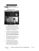
Chucks (118A , 119A) and Face- 19.
plate (110-1A): Chucks and Face-
plates are mounted on the Arbor
Shaft (49A) using a threaded connec-
tion.