
user manual


Page 8SKU 65044
66164
For technical questions, please call 1-800-444-3353.
SPECIFICATIONS
Model 65044 66164
Electrical
Requirements
110/220 V~ ; 60 Hz ; 17/8.5 A
Pre-Wired to 220 V~
Fuses
Fast Acting 2 A (Left)
Fast Acting 1 A (Right)
Lathe Type Metal Working
Motor Speed 1720 RPM
Spindle Speeds 60 to 1550 RPM (18 Speed)
Spindle Taper MT-5
Spindle Bore 1-1/2”
Drive Method V-Belts and Pulleys
V-Belt Markings
B787 L1827
2007-01 (0)
1235-133
Swing Over Bed 12” 13”
Swing Over Gap 18-1/2” 16-1/4”
Center to Center 36” 40-3/4”
Tool Slide Travel 3-1/2” 3”
Tailstock Quill Travel 3-3/4” 4”
Tailstock Quill Taper MT-3
Threading Capacity
Inch = 40
Metric = 29
Inch = 32
Metric = 22
Tool Post Capacity 3/4” 1”
Tool Post Style 4-Way
Mounting Holes
Headstock: 3/8” Diameter (Qty. 4)
Tailstock: 3/8” Diameter (Qty. 2)
65044 ACCESSORIES
Description Qty.
Hex Key Set (3, 4, 5, 6, 8, 10 mm) 1
Tool Box 1
Oil Dropper 1
Exterior Clamping Chuck Jaws (3 pc set) 1
Gear Set 1
Faceplate 1
Slotted Screwdriver 1
Phillips Screwdriver 1
#3 Dead Center 2
#3 Liver Center 1
Drill Chuck and Adapter 1
Tool Post Wrench 1
8” 4-jaw Chuck with Wrench 1
8” 4-jaw Chuck with Wrench 1
66164 ACCESSORIES
Description Qty.
3-Jaw Chuck (Installed on Lathe) 1
4-Jaw Independent Chuck 1
Center Rest (Installed on Lathe) 1
Follow Rest (Installed on Lathe) 1
Face Plate 1
Tool Box 1
L-Style Hex Key Set
(10, 8, 6, 5, 4, 3, 2.5, 2, and 1.5 mm)
1
Center Sleeve with #5 Exterior Morse Taper
& #3 Interior Morse Taper
1
#3 Live Center Morse Taper 1
#3 Dead Center Morse Taper 1
Exterior Clamping Chuck Jaw 3
Pressure Oil Gun 1
T-Handle Chuck Key 2
L-Style Chuck Key 1
Double-Ended 8mm & 10mm Wrench 1
Double-Ended 12mm & 14mm Wrench 1
Double-Ended 17mm & 19mm Wrench 1
T-Handle Female 10mm Square Drive 1
Adjustable Wrench 1
Phillips Head Screwdriver 1
Slot Head Screwdriver 1
25-Tooth Gear 2
49-Tooth Gear 1
71-Tooth Gear 1
UNPACKING
When unpacking, check to make sure
that the item is intact and undamaged. If
any parts are missing or broken, please
call Harbor Freight Tools at the number
shown on the cover of this manual as soon
as possible.
The unpainted surfaces of the Lathe
are coated with a waxy oil to protect them
from corrosion during shipment. Remove
the coating with a solvent cleaner or citrus-
based degreaser. Avoid chlorine-based
solvents since they will damage the paint.
Note: For additional information regarding
the parts listed in the following pages,
refer to the Assembly Diagrams near
the end of this manual.
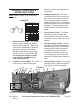
Note: Lathe Stand (either sku 65045 or 66165)
is designed for use with these Gear Head Gap
Bed Lathes (both sku 65044 and 66164). For
shipping efciency, Rear Panel of the Lathe Stand
is packed with this Lathe.
REV 10a
Rear Panel (7) of
the Lathe Stand
65045/66165.