Petol Hydra-Tork U118-13 Operating Manual Gearench P.O. Box 192 4450 South Highway 6 Clifton, Texas 76634 Phone: (254) 675-8651 Fax: (254) 675-6100 © 2005 by GEARENCH.
Table of Contents Petol U118-13 Hydra-Tork Description................................................................................ 1 Warranty ................................................................................................................................. 2 Safe Practices and Procedures............................................................................................... 4 Responsibility.............................................................................................
Petol U118-13 Hydra-Tork Description The U118-13 Petol Hydra-Tork unit was designed for making up and breaking out downhole tools. It is rated for operation on 4" to 24" diameters with a maximum working load of 90,000 ft-lbs. The Petol Pulldown Visetong and Petol Tongvise are adjusted to the different ODs within their range by pulling the Petol Special Chain through the jaw and engaging a cam lock lever. No addition or removal of chain sections is required.
Warranty What Is Covered Gearench tools are expressly warranted to you, the purchaser, to be free of defects in material and workmanship. How Long Coverage Lasts This express warranty lasts for the lifetime of the GEARENCH tool. Warranty coverage ends when the tool becomes unusable for reasons other than defects in workmanship or material. How Can You Get Warranty Service To obtain the benefit of this warranty, contact a GEARENCH sales representative in Clifton, Texas. GEARENCH · 4450 South Highway 6 · P.O.
Forum Selection Clause Any dispute arising out of the sale and/or use of the GEARENCH tool that is the subject of this limited warranty shall be presented in the form of a claim or lawsuit to the offices of GEARENCH in Clifton, Bosque County, Texas. No claim or suit may be brought against GEARENCH, arising out of the sale and/or use of the tool, or arising out of the terms of this warranty, except in such forum.
Safe Practices and Procedures Responsibility "It is the responsibility of the employer to train the employee in the proper selection and usage of tools, chains, etc., and to ensure that they are selected and used in that manner. In many instances, injury results because it is assumed that anybody knows how to use common hand tools. Observations and the record show that this is not the case.
Safety Goggles must always be worn by persons in any area where hand and powered tools are being used. Never apply excess leverage to a wrench or tool by means of a "Cheater Bar". Never strike wrenches and tools with hammers or other objects. All tools should be kept clean, inspected on a regular basis, and replaced when they show signs of wear. Be especially careful not to place yourself in a position that could result in bodily injury in the event of a failure.
Responsibility of Distributors IT IS THE RESPONSIBILITY OF THE PURCHASERS OF GEARENCH PRODUCTS TO CONVEY THE INFORMATION IN THIS PUBLICATION AND ANY OTHER INFORMATION RELATING TO THE INDIVIDUAL PRODUCT, THROUGH THE CHANNELS OF DISTRIBUTION, DOWN TO AND INCLUDING THE INDIVIDUAL USING THE PRODUCT NOTE: In view of the fact that the actual use determines whether safety requirements have been met, the ultimate responsibility to comply rests with the end user.
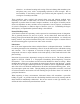
Abrasives - Accelerated wearing and scoring of the articulating chain members (pins and plates) may occur, with a corresponding reduction in chain strength. Due to inaccessibility of the bearing surfaces (pin surfaces and plate apertures), wear and scoring are not readily noticeable. These conditions, when coupled with normal chain wear and inherent residual stress (normally in the chain as constructed), can result in environmentally assisted failure.
Periodic Inspection List for Petol Special Chain 1. PRIOR TO EACH USE, LEAF CHAIN AND TOOLS SHOULD BE INSPECTED FOR SERVICEABILITY AND LUBRICATION. 2. USE ONLY PETOL AND TITAN REPLACEMENT PARTS - NO OTHER PARTS ARE OF COMPARABLE STRENGTH, QUALITY, AND INTERCHANGEABILITY.
9
Safety Precautions 1. Always wear safety goggles to protect eyes. 2. Select the right tool for the job. 3. Keep tools in good condition. 4. Use tools correctly. 5. Keep tools in a safe place. 6. Wear protective clothing, gloves and safety shoes as appropriate. 7. Use lengths of assembled chain. Do not build lengths from individual components. 8. Do not attempt to rework damaged chain by replacing only the components obviously faulty. The entire chain may be compromised and should be discarded. 9.
Installation Location The Petol Hydra-Tork Unit should be located in an area with adequate room to work the downhole tools. The unit may be located indoors or outdoors upon solid level ground or a finished shop floor. No special foundation is required. Setup Locate the hydraulic console in a convenient location and connect the hoses to the main hydraulic cylinder and the lift cylinder.
Operation Controls The operating controls are shown on Figures 1 and 2 on page 16. The disconnect switch is used to disconnect electrical power to the controls. When this switch is on, the motor may be started. The POWER ON switch will start the hydraulic pump motor. It contains an indicator light to show that the motor is on. The POWER OFF switch is used to stop the motor. The FILTER indicator light is used to monitor the hydraulic filter.
TORQUE-PRESSURE CONVERSION TORQUE (ft-lbs) 0 PRESSURE (psig) 0 TORQUE (ft-lbs) 30,000 PRESSURE (psig) 940 10,000 315 31,000 970 11,000 345 32,000 1,000 12,000 375 33,000 1,035 13,000 410 34,000 1,065 14,000 440 35,000 1,095 15,000 470 36,000 1,130 16,000 500 37,000 1,160 17,000 535 38,000 1,190 18,000 565 39,000 1,220 19,000 595 40,000 1,255 20,000 625 45,000 1,410 21,000 660 50,000 1,565 22,000 690 55,000 1,725 23,000 720 60,000 1,880 24,000 750
14
Loading To load the downhole tool in the unit, slide the vise left or right as needed. Adjust the veesaddle to support the tool when set into the vise. Set the tool into the vise. Position the tong for make up or break out as needed and set the tong onto the tool. Adjust the vise and tong as described and latch the vise chain and tong chain. CAUTION: The vee-saddles must be used to support the tool while torquing.
Breaking Out Load the tool and adjust the tong and vise as described above. Fully ratchet the tong. Turn the pressure control knob fully counter-clockwise, engaging the tong. When the tong stops, begin increasing the system pressure by turning the pressure control slowly clockwise. Keep increasing the system pressure until the connection is broken loose or the working load of the tong is reached. Do not exceed the rating of the tong. Consult with GEARENCH as needed for help with the toughest break out jobs.
Recommended Calibration Setpoints Pressure (psig) 0 500 1000 1500 2000 2500 2800 Torque (ft-lbs) 0 15,950 31,910 47,860 63,810 79,770 89,340 Output (volts) 0.000 0.798 1.596 2.393 3.191 3.989 4.
Parts List The following drawings, diagrams, and parts lists describe all parts, which may be needed as replacement items. Where appropriate, standard industrial, electrical, and hydraulic components have been used. Should a standard industrial item need replacing, the item may be purchased locally. To assist you in obtaining parts, the OEM component manufacturer and model numbers are shown on the parts list. Of course, all replacement parts will be supplied by GEARENCH if you prefer to order from us.
Final Assembly Parts List 19
Final Assembly Parts List Item 1 2 3 4 5 6 7 8 9 Qty.
Console Assembly Parts List Item 1 2 3 4 Qty. 1 1 1 30 gal.
Hydraulic Schematic 22
Hydraulic Schematic Parts List Item 1 Qty. 1 Part Number UHCH-P03 Description Pump Make / Model 2 1 UHCH-M11 Motor 3 1 UHCH-M12 Motor coupling 4 1 UHCH-M13 Pump coupling 5 1 UHCH-M04 Coupling insert 6 1 UHCH-M14 Adaptor 7 1 UHCH-V30 Manifold 8 1 UHCH-V08 Relief valve 11 1 UHCH-V21 Regenerative valve 12 1 UHCH-V22 Directional valve 13 2 UHCH-V07 Manifold reducer 14 1 UHCH-V27 P.O. check body 15 1 UHCH-V17 P.O.
Control Panel Parts List Item 1 Qty. 1 Part Number UHCE-S1 Description Push button switch 2 2 UHCE-S2 Push button switch 3 1 UHCE-L1 Pilot light 4 4 UHCE-S3 Push button switch 5 1 UHCE-S5 Selector switch 6 2 UHCE-W23 7 2 UHCE-W25 8 1.50 ft UHCE-W26 3/4” x 45° liquidtight conduit conn.
Main Electrical Panel Parts List Item 1A Qty.
3A 1 UHCE-M1 Starter 3B 3 UHCE-H1 Heater, 230V 3B 3 UHCE-H2 Heater, 380/460V 4A 5 UHCE-W18 Cord connector 4B 5 UHCE-W24 3/8” sealing ring 4C 5 UHCE-W27 3/8” lock nut 5A 2 UHCE-W23 5B 2 UHCE-W25 3/4” x 45° liquidtight conduit conn. 3/4” sealing ring 5C UHCE-W26 6A 2.
Cylinder Carriage Parts List Item 1 2 Qty.
11 1 UHCY-118-C0 Main cylinder 12 1 UHCY-118-RC Cylinder rod clevis 13 2 UHCH-H08 Hose assembly 14 2 UHCH-H09 Hose assembly 15 16 17 2 1 2 UHCY-118-HB HP285 HXRR175 Handle bushing Handle pin Retaining ring Vickers/Aeroquip TZ10HP5N14W24000 Vickers/Aeroquip SH-662-10 Gates 12C2AT-12MP-12FJX-240 Gates 8C2AT-6MP-8FJX-240 Waldes-Truarc 511-175 28 Or equal Or equal Or equal
Vee Saddle Assembly Parts List Item 1 2 3 Qty.
Vise Assembly Parts List Item 1 2 3 4 5 6 7 8 9 10 11 12 13 Qty.
Tong Assembly Parts List Item 1 2 3 4A 4B 5 6 7 8 9 10 11 12 13 Qty.
Petol Special Chain Parts List Item 1 2 3 4 5 6 7 8 9 10 11 Qty.
Electrical Schematic 33