EURO ECO / EURO deluxe DC 2 – EURO ECO DC 2 – EURO deluxe Installation Manual DC 2 DC 2 - Control Unit conforms to DIN EN 12453 Installation Manual
Installation Manual DC 2 – EURO ECO DC 2 – EURO deluxe Table of contents Security instructions and technical data p2 DC – 2 EURO ECO 1-phase 230VAC motor and build-in-starters p3 Layout p4 Programming p5 Optional programming radio control p6 Troubleshooting p7 DC – 2 EURO deluxe 1-phase 230VAC motor and build-in-starters p3 Layout p8 Status display p9 Programming p10-11 Troubleshooting p12 Connection and Accessories for DC – 2 EURO ECO and DC – 2 EURO deluxe Limit switches p13 KDT
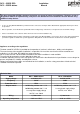
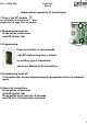
Installation Manual DC 2 – EURO ECO DC 2 – EURO deluxe The door control DC 2 EURO is designed for hold to run control of power operated doors. The basic version is designed for hold to run operation only, and you are not allowed to use the automatic function without using additional safety devices. Safety Directions • In case of using DC 2 EURO with a permanent mains connection, an all-pole main switch with an appropriate back-up fuse must be provided.
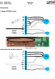
Installation Manual DC 2 – EURO ECO DC 2 – EURO deluxe Connection 1-phase 230VAC motor ▼ ▲ power supply C L N PE PE L1 N M ▲ remove bridge when installing build-in-starters connection for build-in-starters ▼ ▲ C L MS N PE power supply PE L1 N 3
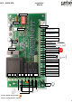
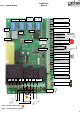
Installation Manual DC 2 – EURO ECO DC 2 – EURO deluxe program DIP green LED radio control push button Limit switch open Limit switch close Pre-limit switch red LED 12 V / brown SKS / green GND / white light module Emergency 24 V GND NC NC NC IMPULSE C STOP DWN N L1 PE PE N L C UP DWN UP Light remove bridge marked with when installing build-in-starters 4
Installation Manual DC 2 – EURO ECO DC 2 – EURO deluxe Turn power on. Checking green light on Turn power off.
Installation Manual DC 2 – EURO ECO DC 2 – EURO deluxe Radio control (maximum 20 transmitters) 1.Plug in the RC module for installation of the receiver module please refer to page 26 at the bottom pushbutton 2.Programming mode on Press button >5 seconds red LED flashes fast 3.Programming red LED Press one button for two seconds red LED flashes long once = stored (or another type of transmitter) and so on. Maximum 20 transmitters. 4.
Installation Manual DC 2 – EURO ECO DC 2 – EURO deluxe Troubleshooting Status red LED Action to take 1x 1, 2, 3 active 2x 1, 2, 3, 7 damaged 3x 4x Off Security RT 1, 2, 3 1, 2, 3 error No power 1,9 1 control installation 6 change module 2 control DIP-switch position 7 change safety edge 3 control pre-wired electrical bridges 8 change photo beam 4 control limit switches 9 change fuse 5 contact dealer 10 change the safety top barrier 7
Installation Manual DC 2 – EURO ECO DC 2 – EURO deluxe RT running time program II program I CT closing time Limit switch open Limit switch close safety module Pre-limit switch red LED status display 12 V / brown SKS / green GND / white radio control green LED push button Emergency 24 V GND light module NC NC NC IN2 IN1 IMPULSE C STOP DWN UP OUT 1 N L1 PE PE N L C UP DOWN Signal light light remove bridge marked with when installing build-in-starters 8
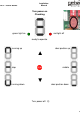
DC 2 – EURO ECO DC 2 – EURO deluxe Installation Manual Turn power on. Checking. red light off green light on ready to operate door postion up running up ▲ stop middle ▼ running down door postion down Turn power off.
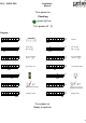
Installation Manual DC 2 – EURO ECO DC 2 – EURO deluxe Program II ■ 1 ■ 2 ■ 3 ■ 4 ■ 5 ■ 6 ■ On Off 1 ■ 2 ■ 3 ■ 4 ■ 5 ■ 6 On Off keypad ■ ■ 1 2 ■ 1 ■ 2 ■ 3 ■ 4 ■ 5 ■ 6 ■ 4 ■ 5 ■ 6 ■ 3 On Off transponder ■ external timer ■ 1 ■ 2 ■ 3 ■ 5 ■ 6 4 ■ 1 ■ 2 ■ 3 ■ 4 5 ■ 6 ■ 2 ■ 3 ■ 4 ■ 5 ■ 6 ■ 3 ■ 4 ■ 5 ■ 6 ■ 4 ■ 5 ■ 6 ■ 5 ■ 6 ■ On Off On Off on On Off radio control green light Program I ■ 1 ■ 2 ■ 3 ■ 4 ■ 5 ■ 6 ■ 1 ■ 2 ■ 3 ■ 4 ■ 5 ■ 6
Installation Manual DC 2 – EURO ECO DC 2 – EURO deluxe RT running time 1 2 3 4 5 6 GB 1 2 3 4 ■ ■ ■ ■ ■ ■ On Off Off Off ■ ■ ■ ■ ■ ■ ■ ■ ■ On Off 8“ ■ ■ ■ ■ ■ ■ ■ ■ ■ ■ ■ ■ ■ ■ ■ On Off 11“ 16“ 12“ 19“ ■ ■ ■ ■ ■ ■ ■ ■ ■ ■ On Off 13“ 22“ ■ ■ ■ On Off ■ ■ ■ On Off 14“ 25“ ■ ■ On Off 15“ 28“ ■ ■ On Off 16“ 31“ ■ ■ On Off 17“ 34“ ■ ■ On Off 18“ 37“ ■ ■ On Off 19“ 40“ ■ ■ On Off 20“ 43“ ■ ■ On Off 21“ 46“ ■ On Off ■
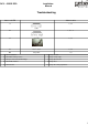
Installation Manual DC 2 – EURO ECO DC 2 – EURO deluxe Troubleshooting Status Display Status red LED Beep Action to take Off No 1, 2, 3, 4 Off No 1, 2, 3 On Yes 7 Off No 1, 2, 3 On Yes 8 On Yes 5 RT error On Yes 1, 2, 3 Safety top barrier Off No 1, 2, 3 On Yes 10 Off No 1, 9 Security active damaged active damaged Relais damaged active Safety top barrier damaged No power 1 control installation 6 change module 2 control DIP-switch position 7 change safety edg
DC 2 – EURO ECO DC 2 – EURO deluxe Installation Manual Connection Limit switch open Limit switch open No limit switches (bridged!) Limit switch close Limit switch close Pre-limit Switch Pre-limit switch ▲ ▲ ▲ open Limit switch open remove bridges when installing build-in-starters open Limit switch open Limit switch close Limit switch close Pre-limit Switch Pre-limit Switch close close pre pre 13
Installation Manual DC 2 – EURO ECO DC 2 – EURO deluxe Connection accessories KDT 3 push button C Stop DWN UP 13 13 21 NO NO NC 14 14 22 DWN Stop UP KDT 2 push button / M Series 2T ▲ C Stop DWN UP remove bridge when installing KDT 3 push button 13 13 NO NO 14 14 UP DWN 14
Installation Manual DC 2 – EURO ECO DC 2 – EURO deluxe M Series 1T 13 NO 14 Emergency stop / KDT 1 21 NC 22 ▲ remove bridge ES Series C Stop DWN UP 15
Installation Manual DC 2 – EURO ECO DC 2 – EURO deluxe J Series C Stop DWN UP 2 P 1 ▲ remove bridge when installing J-Series with Stop J with Stop C Stop DWN UP 2 P 1 21 NC 22 16
Installation Manual DC 2 – EURO ECO DC 2 – EURO deluxe Photo beams LS 1 24V GND NC NC 2 3 4 5 1 2 NA NC C - + 1 RX TX (NO) - + LS 2 ▲ 24V GND NC NC remove bridge 2 3 4 5 GND RX 2 VDD - + GND VDD NC N0 C O M 1 - + 1 TX 17
Installation Manual DC 2 – EURO ECO DC 2 – EURO deluxe LS 2 reflector 24V GND NC NC 1 2 4 3 CND VDD ON CC (NC) RX/TX LS 3 reflector BU ▲ BN remove bridge Cut BK WH GY - + 24V GND NC NC NO C NC UV UB RX/TX 18
Installation Manual DC 2 – EURO ECO DC 2 – EURO deluxe LS 4 24V GND NC NC ▲ remove bridge - + RX - + NC C NO TX 8,2kΩ 12V SKS ■ 8,2kΩ GND 1 ■ 2 ■ 3 ■ 4 ■ 5 ■ 6 ■ 7 On Off 8,2kΩ Safety edge Pro-Sec-O BN BN 12V SKS GR GR RX WH GND WH ■ 1 ■ 2 ■ 3 ■ 4 ■ 5 ■ 6 ■ 7 On Off TX 19
Installation Manual DC 2 – EURO ECO DC 2 – EURO deluxe Court light (230 VAC) / Signal light light DC 2 – EURO deluxe Signal light (230 VAC) Signal S PE L1 N 20
Installation Manual DC 2 – EURO ECO DC 2 – EURO deluxe Optional accessories for DC2 deluxe Cody 1. Wiring Keypad 2. DIP-switch / Program 2 Programming mode on ■ ■ 1 ■ 2 ■ 3 ■ 4 ■ 5 On Off 6 3. Insert codes (10 different codes with 4 or 5 digits) programming & operation Insert code (e.g.) Confirm 1234 Status Display Sound (beep) buttons ___ ___ ▲ / STOP / ▼ 78541 ___ ___ ▲ / STOP / ▼ 5398 ___ ___ ▲ / STOP / ▼ ...
DC 2 – EURO ECO DC 2 – EURO deluxe Installation Manual 4. Programming mode off ■ 1 ■ 2 ■ 3 ■ 4 ■ 5 ■ 6 On Off 5.
Installation Manual DC 2 – EURO ECO DC 2 – EURO deluxe Transponder 1. Wiring 12V SKS GND IN2 IN1 2.
Installation Manual DC 2 – EURO ECO DC 2 – EURO deluxe 3. Programming max. 10 different keys Key No. Position 1 2 3 Maximum 10 keys 4. Programming mode off ■ 1 ■ 2 ■ 3 ■ 4 ■ 5 ■ 6 On Off 5.
Installation Manual DC 2 – EURO ECO DC 2 – EURO deluxe Radio control (maximum 20 transmitters) 1. Plug in the RC module for installation of the receiver module please refer to page 26 at the bottom 2. DIP-switch / Program 2 ■ ■ 1 ■ 2 ■ 3 ■ 4 5 On Off ■ 6 programming mode on 3. Programming press one button for two seconds (or another transmitter) and so on. Maximum 20 transmitters. = 10 = 11 ▲ ▲ = 12 and so on. ▲ 4.
Installation Manual DC 2 – EURO ECO DC 2 – EURO deluxe 5. Cancel transmitters ■ ■ 1 ■ 2 ■ 3 ■ 4 5 ■ 6 On Off press micro push button to choose press mirco push button two seconds transmitter canceled / postion free The door control DC 2 EURO is designed for hold to run control of power operated doors. The basic version is designed for hold to run operation only, and you are not allowed to use the automatic function without using additional safety devices.