
Operation Manual
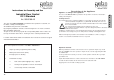

industrial controls
®
industrial controls
®
2314
Processor board
TR 1
S1
L1 L2 L3 N PE U V W N PE 1 2 3
F1
F
D
R1
D4
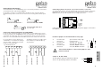
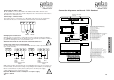
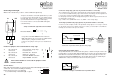
56-57: push button UP-STOP-DOWN-STOP (N.O.)
54-55: push button autom. closing function (N.O.)
53: +24 Volt photo-beam
52: photo-beam
51: photo-beam
50: +15 Volt safety edge
49: Signal safety edge
48: ground safety edge
46-47: pre-limit switch (N.C.)
44-45: external push button STOP (N.C.)
38-39: push button ininside Down (N.O.)
36-37: push button inside UP (N.O.)
42-43: internal-push button STOP (N.C.)
40-41: push button outside Down (N.O.)
34-35: push button outside UP (N.O.)
32-33: limit-switch DOWN (N.C.)
30-31: limit-switch UP (N.C.)
28-29: limit switch half-open (N.C.)
10: ground safety photobeam transmitter
11: +24 safety photobeam transmitter
12: ground safety photobeam transmitter
13: +24 safety photobeam transmitter
14: ground safety photobeam receiver
15: +24 safety photobeam receiver
16-17: safety photo beam outside (N.C.)
18-19: safety photo beaminside (N.C.)
20-21: security limit switch UP (N.C.)
22-23: security limit switch DOWN (N.C.)
24-25: 'Wicket Gate' - motor thermoswitch (N.C.)
26-27: safety devices (e.g.wire rope failure) (N.C.)
}
}
(N.C.)
Power supply
photo beam
ST10
ST9
ST8
ST7
ST6
ST5
ST4
ST3
ST2
ST1
ST13
ST11
ST12
ST16
ST15
ST14
Connection keypad (flat cable)
Setting
Europe-France
DOWN
UP
J1
UK
52
50
48
46
44
42
40
-
+
-
53
51
49
47
45
43
41
+
38
36
34
32
30
28
39
37
35
33
31
29
57
55
56
54
27 25 23 21 19 17 15 13 11
+
26 24 22 20 18 16 14 12 10
-
+
+
-
-
}
}
outside
inside
inside &
outside
Danger Area
visible
}
Set Jumper if Comfort module
is connected
Connection diagramme mainboard - DC 3 Standard
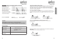
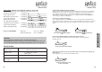
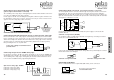
Connecting the mains cable
On the terminals L1, L2, L3. N and PE of the mainboard the mains cable has to be
connected. The value of the fuse must be adapted to the connected motor. If the motor is
blocked it has to activate the fuse.
Connecting a 3-Phase motor
The 3-Phase motor is connected to U, V, W and PE. If the motor has an electric brake
then the brake has to be connected to the terminals W & N of the Brake Module.
PE
U V
W
N
M
3
~
Changing the run direction
After the motor is connected to U, V, W & PE you must control the run direction with the
UP & DOWN push buttons. If the run direction does not match the push buttons arrow then
you have to exchange the wires on the terminals U & V.
Attention: Attend to the run direction of the limit switches !!
Motor
Brake
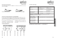
On the screw terminals 14 (-24V) and 15 (+24V) there is another power supply
output available (Receiver safety photo beam)
Important: Maximium current consumption on all power supply
outputs is 500mA.
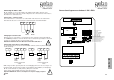
Connecting safety device (anti-trapping)
As safety elements you can use electromecanical elements as well as photo beams
(opto electric elements).
!
!
S
t
a
n
d
a
r
d
14
15 16
17
14
15 18
19
10
11
12
13
Connection photo beam
outside
Supply
voltage
24 V DC
Receiver
Transmitter Transmitter Receiver
Supply
voltage
24 V DC
Contact
(N.C.)
Contact
(N.C.)
Connection photo beam
inside
While using not failure proofed photocells as anti-trapping device it is not necessary to use
Comfort module „S2“ and set the testing corresponding to the installation (see backpage).