
Operation Manual

industrial controls
®
industrial controls
®
1720
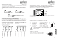
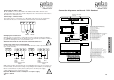
Connecting a traffic light
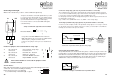
With the DC 3 Standard it is possible to switch a RED traffic light directly.
1
2
3
PE
Ampel
Rot
N
L1
. . . . . . . . . .
. . . . . . . . . .
Using a DC 3 Standard without Comfort module the
RED traffic light may be connected by an additional limit
switch via (N.C.), using the terminals 54/55.
In this case the jumpers on the processor board have to
be set.
Processor board
RED traffic
light
Jumper for RED traffic light without Comfort Modul
To improve the lifetime of the traffic light bulb it is possible
to connect a resistor 39Ω/ 2 watts in series with the bulb of
the traffic light. This resistor fits to a bulb power of 25 watts
(recommended maximum for all geba traffic lights).
If a Comfort module is connected the RED traffic light is
controlled directly.
S
t
a
n
d
a
r
d
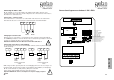
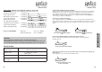
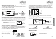
Position of jumpers on the main board for safety edge
1. not connected: opto-electronic safety edge
connected: resistor 8,2 kΩ
2. not connected: dead man UP - direction
connected: impuls UP - direction
3. not connected: dead man DOWN - direction
connected: impuls DOWN - direction
If the Comfort module is connected the jumpers 2 and 3
must be removed.
!
1
23
UK
AUF
AB
F
D
Version France
Only if the Comfort module is connected. The dotted lined bridges have to be
connected - door movement with pre-warning.
Before the door moves a pre-warning
- 3 seconds flashing of red traffic light - is given.
UP
DOWN
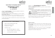
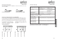
Connection safety edge (optional, only if Comfort module is connected!)
The controlling of the safety edge is managed by the Comfort module and therefore there
is no need for an additional safety edge controler device. According to the EU regulations it
is necessary to test the pneumatic safety edge on EVERY door cycle.
For this purpose the DC 3 has an intelligent testing device which recognises when the door
has finished the closing cycle.
(resp. switches from „STOP with reverse“ to „STOP“ - electr. safety edge).
In order to test the complete circuit of the pneumatic safety edge, it is necessary to connect
(on the inside of the pressure switch enclosure) a resistor (3,3 to 8,2 kΩ) in series with the
normally closed contact of the pressure switch.
Connection of pressure switch (pneum. safety edge)
48
49
P
3,3 bis 8,2 kΩ
Connecting a pneumatic safty edge (optional, only if Comfort module is connected!)
!
Check settings of Jumper on
mainboard (see page 20)
and DIP-Switches
on Comfort module !
(see backpage)
3,3 to 8,2 kΩ
Connection of bridge on terminals 46 & 47 pre-limit switch.
46
47
Connecting the pre-limit switch
The pre-limit switch has to be mounted at the door guides, so that the closing door reaches the
pre-limit switch (e.g. extra pre-limit switch PS-ECO about 5 cm above the ground. After the pre-
limit switch has reacted the unit controlls the exact reaction of the safety edge as well as the
opening of the limit switch in DOWN direction. The pre-limit switch can also be activated by an
additional N.C. contact, the contact opens about. 5 cm above the ground.