
Operation Manual

316
industrial controls
®
industrial controls
®
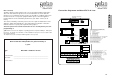
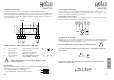
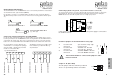
Connecting external push-buttons UP, STOP, DOWN
For the use from outside of ther DC 3 an external 3x bushbutton unit (e.g. KDT-3) can be
connected
36
37 44
45
38 39
external push button unit
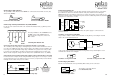
Connection safety edge (optional, only if Comfort module is connected!)
The controlling of the safety edge is managed by the Comfort module and therefore there is
no need for an additional safety edge controler device. According to the EU regulations it is
necessary to test the pneumatic safety edge on EVERY door cycle, therefore it is possible
to connect a pre-limit switch to the DC 3, which starts the intelligent test procedure (resp.
with an electric safety bar, changes the the function from „STOP with reverse“ to „STOP“).
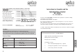
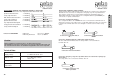
Connecting an electro mechanical safety edge (optional, only if Comfort modul is connected!)
In order to test the complete circuit of the pneumatic safety edge, it is necessary to connect
(on the inside of the pressure switch enclosure) a resistor (3,3 up 8,2 kΩ) in series with the
normally closed contact of the pressure switch.
Connection of a electro-mechanical safety edge
48
49
P
3,3 bis 8,2 kΩ
Connecting of limit switches
The potentialfree limit switches UP & DOWN are connected to the terminals 30 & 31 (UP)
and 32 & 33 (DOWN).
Connection limit switch UP
Connection limit switch DOWN
30
31
32
33
The two pushbuttons UP and DOWN have to
be N.O. contact. If the STOP function is
connected in the safety circle, it has to be
N.C. contact.
!
Check settings of Jumper on
mainboard (see page 9)
and of DIP-Switches
on Comfort module
(see backpage )!
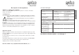
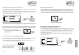
connection pull switch
Connecting a pull switch
On the screw terminals 56 & 57 a pull switch (NO contact) can be connected.
56
57
automatic closing function (ON /OFF)
It is possible to switch or switch off the automatic closing time by connecting an external
timer to the screw terminals 54 & 55.
54
55
54
55
54
55
automatic closing function ON automatic closing function OFF
In the event of the automatic closing function being switched on permanently the screw
terminals 54 & 55 have to be bridged.
The function of the pull switch is
UP/STOP/DOWN/STOP.
d
e
L
u
x
e
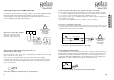
Connecting a photo-cell
To connect a photo-beam to cover the ‘drive through’ area the photo-beam is connected to
the terminals 51, 52 & 53. If the infrared beam of the photo-beam is broken during the
DOWN direction the door will stop and reverse to a fully open position. It is possible to con-
figure the Comfort module so that when the photo-beam is activated by traffic the automatic
closing time is reduced to 5 seconds.
Using a photo-cell with receiver and transmitter, the power supply is connected to the
terminals 52 & 53.
51
52
53
NC
CC
GND
+
Spannungs-
versorgung
Steuerlogik
button
UP
button
STOP
button
DOWN
logic board
power
supply
3,3 - 8,2 kΩ