
Operation Manual

industrial controls
®
industrial controls
®
730
E
C
O
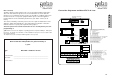
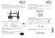
The pre-limit switch has to be mounted at the door guides, so that the closing door reaches
the pre-limit switch (e.g. extra pre-limit switch PS-ECO) about 5 cm above the ground.
After the pre-limit switch has reacted the unit controlls the exact reaction of the safety edge
as well as the opening of the limit switch in DOWN direction. The pre-limit switch can also be
realized by an additional opener contact, the contact must open about 5 cm above the ground.
46
47
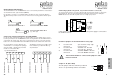
Connection pre-limt switch
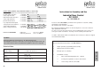
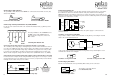
Connecting an electro mechanical safety edge
(optional, only if Comfort module is connected!)
The controlling of the safety edge is managed by the Comfort module and there is therefore
no need for an additional safety edge managenment device. According to the EU regulati-
ons it is necessary to test the pneumatic type safety edge on EVERY movement cycle.
For this purpose the DC 3 has an intelligent testing device which recognises when the door
has finished the closing cycle.
In order to check it is necessary to connect a resistor on the opposite end of the safety
edge (cable connection).
Connection of an electro-mechanical safety edge
48
49
8,2 kΩ
!
Check settings ofJumper on
mainboard (see page 9)
and DIP-Switches
on Comfort module !
(see backpage)
Mounting of pre-limit switch
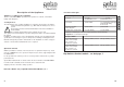
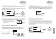
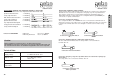
Connecting an opto-electric FRABA-Safety edge
It is possible to connect to the DC 3 an electric, pneumatic or opto-electronic (FRABA) type Safety
Edge device directly to the terminals 48, 49 & 50 without any specific control boxes.
The controlling of the safety edge is managed by the Comfort module and therefore there is no
need for an additional safety edge management device.
48
49 50
weiss
grün
braun
weiss grün
braun
Opto-electric safety edge - FRABA
terminal 48 = Safety edge (-GND)
terminal 49 = Safety edge (Signal)
terminal 50 = Safety edge (+ 15V
)
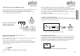
Connecting an electro mechanical safety edge
The controlling of the safety edge is managed by the Comfort module and there is therefore
no need for an additional safety edge controller.
For this purpose the DC 3 has an intelligent testing device which recognises when the door
has finished the closing cycle. In order to check it is necessary to connect a resistor on the
opposite end of the safety edge (cable connection).
48
49
8,2 kΩ
!
Connection of a electro-mechanical safety edge
Check settings of Jumper on
mainboard (see page 32)
and of DIP-Switches
on Comfort module
(see backpage )!
white
white
green
brown
green
brown
Because the function of the safety-edges is automatically checked by the Comfort module
there is normally no need to test it. In this case the screw terminals 46 & 47 of the pre-limit
switch can be bridged. In situations where the rubber of the safety edge needs to touch the
ground you have to control this with a pre-limit switch (adjustment 5 cm above ground),
thus preventing the door to stop and return.
Connection pre-limit switch if using an electric- or opto-electronic safety edge
Connection of bridge on terminals 46 & 47
pre-limit switch.
46
47
3,3 - 8,2 kΩ
3,3 - 8,2 kΩ