
Operation Manual

industrial controls
®
industrial controls
®
928
E
C
O
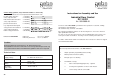
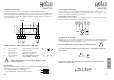
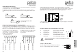
Connecting the limit switches
The two limit switches UP and DOWN have to be connected as potentialfree contacts at the
screw terminals 30/31 (UP) and 32/33 (DOWN).
It is possible to connect a second limit switch to the DC 3 de Luxe for the UP direction.
Two different UP positions can be choosen on the front of housing (summer-/winter positi-
on).
28
29
Connection limit switch UP 1
Connection limit switch UP 2
(e.g. half open)
Connection limit switch DOWN
30
31
32
33
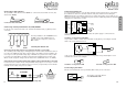
Connecting external push-buttons UP, STOP, DOWN
For the use from outside of the DC 3 an external switch (e.g. key-switch) can be connec-
ted. The push buttons UP and DOWN must have closing function. As the STOP function is
connected in the safety circle, it has to be connected as an opener. In case two 2x push-
buttons are connected, STOP inside and STOP outside must be switched in serial mode.
34
35 42
43
40 41
36
37 44
45
38 39
Push button module 1
push button UP
push button STOP
push button DOWN
Push button module 2
push button UP
push button STOP
push button DOWN
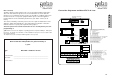
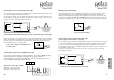
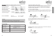
Position of jumpers on the main board for safety edge
1. not connected: opto-electronic safety edge
connected: resistor 8,2 kΩ
2. not connected: dead man UP - direction
connected: one touch UP - direction
3. not connected: dead man DOWN - direction
connected: one touch DOWN - direction
If the Comfort module is connected the jumpers 2 and 3
must be removed.
!
1
23
UK
AUF
AB
F
D
Jumper F - D (DC 3 ECO)
The two jumpers F-D must remain in position D.
There is no pre-warning element connectable.
UP
DOWN
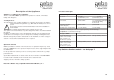
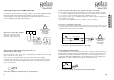
Connecting a photo-cell (optional, only if Comfort module is connected!)
To connect a photo-beam to cover the ‘drive through’ area the photo-beam is connected to
the terminals 51, 52 & 53. If the infrared beam of the photo-beam is broken during the
DOWN direction the door will stop and reverse to a fully open position.
Using a photo-cell with receiver and transmitter, the power supply is connected to
the terminals 52 & 53.
51
52
53
NC
CC
GND
+
Spannungs-
versorgung
Steuerlogik
logic board
supply
voltage
It is not possible to use the switch in case
of malfunction of a security device (Danger
area not visible) - optional, only if Comfort
module is connected 5V DC/
e.g. Schleifendetektoren.
The Danger area has to be visible, dead-
mans function is possible 24V DC/ e.g.
3x push button.