
User`s manual


6
EDID MANAGEMENT MODES
EDID Modes
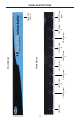
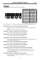
The diagram below illustrates the 8 DIP switch bank.
DIP SWITCH Function
1 EDID Mode
2 EDID Mode
3 N/A
4 N/A
5 EDID Mode
6 N/A
7 EDID Mode
8 N/A
Use DIP switches 1, 2, 5, and 7 to select the desired EDID management mode.
EDID Mode 0 (Switch 1=OFF Switch2=OFF Switch5=ON)
• Edid is copied from the device connected to the fi rst active hdmi output
port.
• All features newer that HDMI 1.2 are cleared.
EDID Mode 1 (Switch 1=ON Switch2=OFF Switch5=ON)
• Same as Mode 0 and adds basic audio support.
EDID Mode 2 (Switch 1=OFF Switch2=ON Switch5=ON)
• Same as Mode 0 and adds full audio support.
EDID Mode 3 (Switch 1=ON Switch2=ON Switch5=OFF)
• EDID is generated based on the common video and audio features of all
of the connected output devices.
EDID Mode 4 (Switch 1=OFF Switch2=ON Switch5=OFF)
• Same as Mode 3 and adds basic audio support.
EDID Mode 5 (Switch 1=ON Switch2=OFF Switch5=OFF)
• Same as Mode 3 and adds full audio support.
EDID Mode 6 (Switch 1=OFF Switch2=OFF Switch5=OFF) DEFAULT
• EDID is generated based on the common video features of all of
the connected devices and the combined audio features of all of the
connected output devices.
EDID Mode 7 (Switch 1=ON Switch2=ON Switch5=ON)
• EDID is passed unmodifi ed from the device connected to the fi rst
active output port.
1
2
3
4
5
6
7
8
v. 2015