® 4x4 Matrix for HDMI® 1.3 EXT-HDMI1.3-444 User Manual www.gefen.
ASKING FOR ASSISTANCE Technical Support: Telephone Fax (818) 772-9100 (800) 545-6900 (818) 772-9120 Technical Support Hours: 8:00 AM to 5:00 PM Monday through Friday, Pacific Time Write To: Gefen, LLC c/o Customer Service 20600 Nordhoff St Chatsworth, CA 91311 www.gefen.com support@gefen.com Notice Gefen, LLC reserves the right to make changes in the hardware, packaging and any accompanying documentation without prior written notice. 4x4 Matrix for HDMI 1.
CONTENTS 1 Introduction 2 Operation Notes 3 Features 4 Panel Layout 5 Panel Descriptions 6 Connecting And Operating The 4x4 Matrix for HDMI 1.3 7 EDID Modes 8 RMT-16IR Remote Description 9 4x4 Matrix for HDMI 1.
INTRODUCTION Congratulations on your purchase of the 4x4 Matrix for HDMI 1.3. Your complete satisfaction is very important to us. Gefen Gefen delivers innovative, progressive computer and electronics add-on solutions that harness integration, extension, distribution and conversion technologies.
OPERATION NOTES READ THESE NOTES BEFORE INSTALLING OR OPERATING THE 4X4 MATRIX FOR HDMI 1.3 • You should connect all the cables and power supply prior to connecting power to the HDMI sources and 4x4 Matrix for HDMI 1.3. • When powering the sources, the display needs to point to the source input. • 3D content can be displayed by connecting a 3DTV and 3D source. • Display information (EDID) is needed by the source devices to determine the capabilities of the connected display.
FEATURES Supported HDMI 1.3 Features: • • • • 225 MHz (up to 12 bit YUV 444 @ 1080p) Deep Color Dolby TrueHD and DTS-HD Master Audio Lip Sync Features: • Route any of four (4) Hi-Def sources to any four (4) HDTV displays, independently. • Supports resolutions up to 1080p, 1920x1200, and 2K • 3DTV pass-through • Color Space Conversion • IR Remote Control • RS-232 Control • Supports DVI sources and DVI displays with an HDMI to DVI converter cable or adapter.
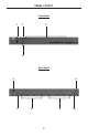
PANEL LAYOUT Front Panel 1 2 3 4 Back Panel 5 6 7 8 9 4 10
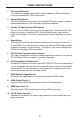
PANEL DESCRIPTIONS 1 IR (Infrared) Receiver This receiver will accept command for switching between HDMI input devices using the included RMT-16IR remote control. 2 Power LED Indicator This LED will become active once the included 5V DC power supply is properly connected between the unit and a open wall power receptacle. 3 Display 1-4 Selected Input LED Indicator There is a set of 4 LEDs for each of the four output ports.
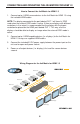
CONNECTING AND OPERATING THE 4X4 MATRIX FOR HDMI 1.3 How to Connect the 4x4 Matrix for HDMI 1.3 1. Connect up to 4 HDMI source devices to the 4x4 Matrix for HDMI 1.3 using the included HDMI cables. NOTE: The display connected to the port labeled OUT 1 will have its EDID used when the external EDID mode is active. If there are displays with different resolutions in the setup it is recommended that the display with the lowest resolution be placed on the HDMI port labeled OUT 1.
EDID MODES EDID. What is it and what is it used for? Under normal circumstances, an source device (digital and analog) will require information about a connected device/display to assess what resolutions and features are available. The source can then cater its output to send only resolutions and features that are compatible with the attached device/ display.
RMT-16IR REMOTE DESCRIPTION The RMT-16IR remote control will allow the user to select which source will be routed to which output. Each of the 4 outputs are assigned a group of 4 buttons that will correspond to the 4 source inputs. Please use the information below when selecting the desired source for each display.
4X4 MATRIX FOR HDMI 1.3 REMOTE INSTALLATION Installing the IR Remote Control Battery 1. Remove the battery cover on the back of the IR Remote Control unit. 2. Insert the included battery into the open battery slot. The positive (+) side of the battery should be facing up. 3. Replace the battery cover. The Remote Control unit ships with two batteries. One battery is required for operation and the other battery is a spare.
IR CHANNEL CONFIGURATION How to Resolve IR Code Conflicts In the event that IR commands from other remote controls conflict with the supplied RMT-16IR remote control, changing the remote channel will alleviate this issue. The RMT-16IR remote control has a bank of DIP switches for configuring the remote channel that both units use to communicate. The 4x4 Matrix for HDMI 1.
RS-232 SERIAL COMMUNICATION CONTROL 54321 12345 9876 6789 Only Pins 2 (RX), 3 (TX), and 5 (Ground) are used on the RS-232 serial interface Binary Table ASCII Corresponding RMT16-IR Button 1 1 2 2 3 3 4 4 5 5 6 6 7 7 8 8 Binary ASCII 0011 0001 0011 0010 0011 0011 0011 0100 0011 0101 0011 0110 0011 0111 0011 1000 9 a b c d e f g Corresponding RMT16-IR Button 9 10 11 12 13 14 15 16 Binary 0011 1001 0110 0001 0110 0010 0110 0011 0110 0100 0110 0101 0110 0110 0110 0111 Additional Features ASCII X o
SPECIFICATIONS Video Amplifier Bandwidth ....................................................................... 225 MHz Input Video Signal ................................................................................... 1.2 V p-p Input DDC Signal .............................................................................. 5 V p-p (TTL) Single Link Range ................................................................... 1080p/1920 x 1200 HDMI Connector .................................................
WARRANTY Gefen warrants the equipment it manufactures to be free from defects in material and workmanship. If equipment fails because of such defects and Gefen is notified within two (2) years from the date of shipment, Gefen will, at its option, repair or replace the equipment, provided that the equipment has not been subjected to mechanical, electrical, or other abuse or modifications.
Rev A5 20600 Nordhoff St., Chatsworth CA 91311 1-800-545-6900 818-772-9100 www.gefen.com Pb This product uses UL listed power supplies. fax: 818-772-9120 support@gefen.