4x4 HDTV KVM Matrix USER MANUAL www.gefen.
ASKING FOR ASSISTANCE Technical Support: Telephone (818) 884-6294 (800) 545-6900 Fax (818) 884-3108 Technical Support Hours: 8:00 AM to 5:00 PM Monday through Friday. Write To: Gefen Inc. C/O Customer Service 6265 Variel Ave. Woodland Hills, CA 91367-9897 Notice Gefen Inc. reserves the right to make changes in the hardware, packaging and any accompanying documentation without prior written notice. The 4x4 HDTV KVM Matrix is a trademark of Gefen Inc. © 2007 Gefen Inc.
TABLE OF CONTENTS 1 Introduction / Operation Notes 2 Features 3 Panel Layout 4 Using the 4x4 HDTV KVM Matrix 5 RMT16-IR Installation 6 Dip Switch Guidelines 7 IR Codes 8 RS-232 Interface 9 4x4 HDTV KVM Matrix Rack Mount Diagram 10 Specifications 11 Terminology 12 Warranty
INTRODUCTION Thank you for purchasing the 4x4 HDTV KVM Matrix. The 4x4 HDTV KVM Matrix switches four DVI sources to any four DVI displays. Now you can easily switch four cross-platform computers to four digital displays. Our 4x4 HDTV KVM Matrix provides a simple, reliable and highly effective method of creating multiple computer workstations, with each workstation capable of accessing any one of the computers or sources at any time by remote control.
FEATURES Features • Increases your productivity by providing you with access to four computers from four workstations • Maintains highest resolution digital video with no loss of quality • Supports either PC or Mac USB keyboards/mice • USB 2.
Connects to 5VDC Power Supply 3 DVI Inputs USB & Audio Inputs DVI Outputs USB & Audio Outputs IR Extender Eye Port Back Panel Display 1 Display 4 Display 2 Display 3 LED Indicator LED Indicator LED Indicator LED Indicator IR Sensor Front Panel Connects to 24VDC Power Supply RS232 Controller Port Power Indicator PANEL LAYOUT
USING THE 4X4 HDTV KVM MATRIX 1 Connect all the sources to the DVI inputs on the 4x4 HDTV KVM Matrix, using the supplied cables. 2 Connect the HDMI/DVI displays to the outputs on the 4x4 HDTV KVM Matrix. 3 Connect the 24VDC powersupply to the 4x4 HDTV KVM Matrix. 4 Controlling the 4x4 HDTV KVM Matrix using the RMT16-IR: Pressing Buttons... 1-4 5-8 9-12 13-16 Switches...
RMT16-IR INSTALLATION 1. Remove battery cover from the back of the RMT16-IR remote. 2. Verify that dip switches 1 & 2 are in the down (OFF) position. 3. Insert the battery, hold the battery so that you can see the positive side facing up. The side that is not marked must be facing down. 4. Test the RMT16-IR remote by pressing ONLY one button at a time. The indicator light on the remote will flash once each time you press a button.
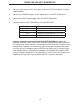
DIP SWITCH GUIDELINES Inside the 4x4 HDTV KVM Matrix is a bank of Dip Switches. Below is a table describing their functions. By default, all switches are set to the Off position.
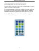
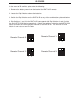
IR CODES In the event of IR conflicts, please do the following: 1. Remove the battery cover from the back of the RMT16-IR remote. 2. Locate the Dip Switches above the batteries 3. Switch the Dip Switches on the RMT16-IR to any of the combinations pictured below. 4. Dip Switches 1 and 2 in the RMT16-IR correspond with Dip Switches 3 and 4 inside the 4x4 HDTV KVM Matrix respectively. Switch the switches inside the 4x4 HDTV KVM Matrix to match the same Remote Channel as the RMT16-IR.
RS-232 INTERFACE Send Transmit Ground Binary Table ASCII Corresponding RMT16-IR Button 1 1 2 2 3 3 4 4 5 5 6 6 7 7 8 8 Hex ASCII 0011 0001 0011 0010 0011 0011 0011 0100 0011 0101 0011 0110 0011 0111 0011 1000 9 a b c d e f g Corresponding RMT16-IR Button 9 10 11 12 13 14 15 16 Hex 0011 1001 0110 0001 0110 0010 0110 0011 0110 0100 0110 0101 0110 0110 0110 0111 RS232 Settings Bits per second ......................................................................................................
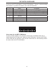
4X4 HDTV KVM MATRIX RACK MOUNT DIAGRAM 9
SPECIFICATIONS Video Amplifier Bandwidth..................................................................................1.65 Gbps Input Video Signal...........................................................................................1.2 volts p-p Input DDC Signal......................................................................................5 volts p-p (TTL) Single Link Range................................................................................1080p/1920 x 1200 DVI Connector.........
TERMINOLOGY DDC Short form for Display Data Channel. It is a VESA standard for communication between a monitor and a video adapter. Using DDC, a monitor can inform the video card about its properties, such as maximum resolution and color depth. The video card can then use this information to ensure that the user is presented with valid options for configuring the display. DDWG Digital Display Working Group DDWG are the creators of the DVI specification. DVI Digital Visual Interface.
WARRANTY Gefen Inc. warrants the equipment it manufactures to be free from defects in material and workmanship. If equipment fails because of such defects and Gefen Inc. is notified within two (2) year from the date of shipment, Gefen Inc. will, at its option, repair or replace the equipment, provided that the equipment has not been subjected to mechanical, electrical, or other abuse or modifications.