
User manual


5
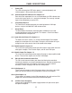
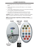
1 Power LED
This LED indicator glows RED when power is connected properly and
suffi cient power is being received by the Matrix.
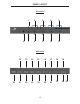
2-5 Selected Input LED Indicators For Outputs 1-4
Each of the four output ports has an associated bank of 4 LED indicators that
shows which input source 1-4 is active for that output. The currently selected
input will be indicated by an active LED.
6 IR (Infrared) Receiver
This Receiver will accept commands for switching between VGA input
devices using the included RMT-16IR remote control.
7 Reset Button
The Reset button momentarily interrupts power, rebooting the unit and
resetting operational settings to defaults. This feature is useful if the Matrix
somehow becomes unresponsive.
8-11 Input Selection Button For Outputs 1-4
This button will set the source (1-4) for the indicated output. Each labeled
output on the front panel has this button. Each press of this button will cycle
through the four input sources that will be routed to that output.
12-15 Audio Inputs For Inputs 1-4
This 3.5mm mini-jack analog stereo input will accept a single audio source for
routing to the outputs. There are four inputs, one for each VGA input.
16-19 Audio Output For Outputs 1-4
This 3.5mm mini-jack analog stereo output will accept a single amplifi ed audio
device. There are four outputs, one for each VGA output.
20 RS-232 Serial Communications Port
This DB-9 serial communications port allows the Matrix to be controlled
remotely by computers or control automation devices. Remote control devices
send routing commands to the Matrix via this port in the form of ASCII
characters. Please see page 10 for RS-232 Confi guration.
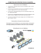
21-24 VGA Inputs 1-4
These inputs will accept a single VGA source device. Any of these four VGA
inputs can then be routed in any combination to the four VGA outputs.
25-28 VGA Outputs 1-4
These outputs will accept a single VGA output device. Any of these four VGA
outputs can select and view one of the four VGA/Audio inputs.
29 24V DC Power Receptacle
Connect the included 24V DC power supply between this port and an open
wall power receptacle.
PANEL DESCRIPTIONS