® CAT5-5600HD EXT-CAT5-5600HD User Manual www.gefen.
ASKING FOR ASSISTANCE Technical Support: Telephone (818) 772-9100 (800) 545-6900 Fax (818) 772-9120 Technical Support Hours: 8:00 AM - 5:00 PM Monday - Friday, Pacific Time Write To: Gefen LLC c/o Customer Service 20600 Nordhoff St Chatsworth, CA 91311 www.gefen.com support@gefen.com Notice Gefen LLC reserves the right to make changes in the hardware, packaging and any accompanying documentation without prior written notice.
CONTENTS 1 Introduction 2 Operation Notes 3 Features 4 Sender Panel Layout 5 Sender Panel Descriptions 6 Receiver Panel Layout 7 Receiver Panel Descriptions 8 Connecting and Operating the CAT5-5600HD 8 Wiring Diagram 9 Adjusting the Signal Quality 10 DIP Switch Configuration 13 Network Cable Wiring Diagram 14 Rack Mount Installation 15 Specifications 16 Warranty
INTRODUCTION Congratulations on your purchase of the CAT5-5600HD. Your complete satisfaction is very important to us. Gefen Gefen is a unique product line catering to the growing needs for innovative home theater solutions. We specialize in total integration for your home theater, while also focusing on going above and beyond customer expectations to ensure you get the most from your hardware. We invite you to explore our distinct product line and hope you find your solutions.
OPERATION NOTES READ THESE NOTES BEFORE INSTALLING OR OPERATING THE CAT5-5600HD • CAT-6a cables can be used up to 200 feet (60 meters). • CAT-5e cables can be used up to 150 feet (45 meters). • Shielded (STP) CAT-5e/CAT-6a is recommended. However, unshielded (UTP) CAT-5e/CAT-6a is acceptable. NOTE: Shielded cable has an advantage by providing immunity to Electromagnetic Interference (EMI), cell phones and A/C motors. • The CAT5-5600HD only supports DVI-D signals. Analog DVI content is not supported.
FEATURES Features • Extends two DVI sources to 200 feet (60 meters) up to 1080p or 1920x1200 (using CAT-6a cables) • Extends USB 2.0 up to 200 feet (60 meters) • Backward-compatible with USB 1.1 devices • Works with any computer using DVI and USB • Supports the DDWG standard for DVI compliant monitors • Rack-mountable (includes rack ears) Package Includes (1) CAT5-5600HD - Sender Unit (1) CAT5-5600HD - Receiver Unit (2) 6 ft. DVI cable (M-M) (1) 6 ft.
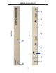
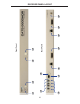
1 3 4 5 6 2 4 7 Back Panel Front Panel 8 9 10 SENDER PANEL LAYOUT
SENDER PANEL DESCRIPTIONS 1 Power / Link 2 Indicator When power is applied to the Sender Unit, this LED will glow bright red. Once a DVI source is connected to the DVI 2 input, this LED will glow bright green. 2 Link 1 Indicator When power is applied to the Sender Unit, this LED will glow bright red. Once a DVI source is connected to the DVI 1 input, this LED will glow bright green. 3 USB Input Port Connect the USB host device to this port.
5 1 6 2 7 8 9 3 6 10 Back Panel 4 Front Panel 11 12 13 RECEIVER PANEL LAYOUT
RECEIVER PANEL DESCRIPTIONS 1 Power / Link 2 Indicator When power is applied to the Receiver Unit, this LED will glow bright red. Once a link has been established between the Sender Unit and the Receiver Unit, the LED glows bright green. 2 Link 2 EQ Trim Pot The EQ trim pot is used to equalize the signal on the DVI 2 output. See page 9 for details. 3 Link 1 Indicator When power is applied to the Receiver Unit, this LED glows bright red.
CONNECTING AND OPERATING THE CAT5-5600HD How to Connect the CAT5-5600HD 1. Connect the DVI source to the Sender Unit using the included DVI cable. Another DVI cable can be used to connect a second DVI source to the Sender Unit. 2. Connect the included USB cable from the computer to the Sender Unit. 3. Connect the DVI display(s) and USB devices to the Receiver Unit. Up to four (4) USB devices can be connected to the Receiver Unit. 4.
CONFIGURING THE CAT5-5600HD Adjusting the Signal Quality The CAT5-5600HD has two EQ trim pots on the front of the Receiver Unit to compensate for the extension distance and cable skew found in different CAT-5e / CAT-6a cabling brands. EQ 1 corresponds to DVI 1 and EQ 2 corresponds to DVI 2. If there is no output video or if output video contains video artifacts and/or video noise such as snow, use the steps below to adjust the EQ trim pot(s). 1.
DIP SWITCH CONFIGURATION Sender Unit The Gefen CAT5-5600HD contains DIP switches on the bottom of the Sender Unit. Each DIP switch performs a different function. Two DIP switches located on the bottom of the CAT55600HD Sender Unit. There are two sets of DIP switches on the Sender Unit: One for each DVI input. DIP Switch 1 - Green Mode (Default = ON) • OFF - Enable Green Mode When DIP switch 1 on the Sender Unt is set to the OFF position, the CAT55600HD is placed in Green Mode.
DIP SWITCH CONFIGURATION Receiver Unit The Gefen CAT5-5600HD contains DIP switches on the bottom of the Sender Unit. Each DIP switch performs a different function. The four DIP switches located on the bottom of the CAT55600HD Receiver Unit. There are two sets of DIP switches on the Receiver Unit: One for each DVI output.
DIP SWITCH CONFIGURATION Receiver Unit DIP Switch 2 - Color Depth (Default = OFF) • OFF - 8-bit Color Disables Deep Color in the EDID. Deep Color management is only available when Local EDID is being used (DIP 1 = OFF). • ON - 12-bit Color Set DIP switch 2 to the ON position to enable Deep Color support. In Passthrough EDID Mode, setting DIP switch 2 to the ON position has no effect since all EDID information is passed through. DIP Switch 3 - Not Used • Reserved for future expansion.
NETWORK CABLE WIRING DIAGRAM Gefen recommends the TIA/EIA-568-B wiring option. Please adhere to the table below when field-terminating the CAT-5e / CAT-6a cable for use with Gefen products. Pin Color 1 Orange / White 2 Orange 3 Green / White 4 Blue 5 Blue / White 6 Green 7 Brown / White 8 Brown CAT-5e / CAT-6a cabling comes in stranded and solid core types. Gefen recommends using solid core cabling. It is recommended to use one continuous run from one end to the other.
RACK MOUNT INSTALLATION Rack mount ears are provided for installation of this unit into a 1U rack mount space. 1. 2. 3. 4. Locate the side screws on the unit. Remove the front 2 screws that are located closest to the front of the unit. Using the removed screws, screw the rack mounting bracket into the unit. Repeat the procedure on the opposite side of the unit.
SPECIFICATIONS Maximum Pixel Clock................................................................................165 MHz Input Video Signal.....................................................................................1.2 V p-p Input DDC Signal................................................................................5 V p-p (TTL) Digital Video Inputs (Sender).............................................(2) DVI-I, 29-pin, female Digital Video Outputs (Receiver)...................................
WARRANTY Gefen warrants the equipment it manufactures to be free from defects in material and workmanship. If equipment fails because of such defects and Gefen is notified within two (2) years from the date of shipment, Gefen will, at its option, repair or replace the equipment, provided that the equipment has not been subjected to mechanical, electrical, or other abuse or modifications.
Pb