
User manual


7
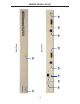
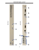
RECEIVER PANEL DESCRIPTIONS
1 Power / Link 2 Indicator
When power is applied to the Receiver Unit, this LED will glow bright red. Once
a link has been established between the Sender Unit and the Receiver Unit, the
LED glows bright green.
2 Link 2 EQ Trim Pot
The EQ trim pot is used to equalize the signal on the DVI 2 output. See page 9
for details.
3 Link 1 Indicator
When power is applied to the Receiver Unit, this LED glows bright red. When
the link has been established between the Sender Unit and the Receiver Unit,
this LED glows bright green.
4 Link 1 EQ Trim Pot
The EQ trim pot is used to equalize the signal on the DVI 1 output. See page 9
for details.
5 USB Output Ports (1 - 4)
Connect USB devices to these ports.
6 USB Connection Indicators (1 - 4)
These LEDs will turn bright green when USB devices have been connected.
7 USB / CAT-6 Link Input
Connects the USB / CAT-6 Link on the Receiver Unit to the USB / CAT-6 Link on
the Sender Unit using CAT-6 cabling.
8 USB Link Indicator
This LED will turn bright green once a USB link between the Sender Unit and
the Receiver Unit has been made. If the USB link is lost, this LED will glow
bright red.
9 Video 1 / CAT-6 Link Input
Connects the Video / CAT-6 Link on the Receiver Unit to the Video / CAT-6 Link
on the Sender Unit using CAT-6 cabling.
10 DVI 1 Output
Connect a DVI display to this DVI-I connector.
11 Video 2 / CAT-6 Link Output
Connects the Video 2 / CAT-6 Link on the Receiver Unit to the Video 2 / CAT-6
Link on the Sender Unit using CAT-6 cabling.
12 DVI 2 Input
Connect a DVI display to this DVI-I connector.
13 5 V DC Locking Power Connector
Connect the included 5 V DC locking power supply to this connector.