® E T-2DVI-DLKVM-CAT6 EX User Manual www.gefen.
ASKING FOR ASSISTANCE Technical Support: Telephone Fax (818) 772-9100 (800) 545-6900 (818) 772-9120 Technical Support Hours: 8:00 AM to 5:00 PM Monday through Friday, Pacific Time Write To: Gefen, LLC c/o Customer Service 20600 Nordhoff St Chatsworth, CA 91311 www.gefen.com support@gefen.com Notice Gefen, LLC reserves the right to make changes in the hardware, packaging and any accompanying documentation without prior written notice.
CONTENTS 1 Introduction 2 Operation Notes 3 Features 4 Sender Unit Layout 5 Sender Unit Descriptions 6 Receiver Unit Layout 7 Receiver Unit Descriptions 9 Connecting the 2x Dual Link DVIKVM Extender Over CAT-6a 9 Wiring Diagram 10 DIP Switch Configuration 12 Adjusting the Signal Quality 13 Network Cable Wiring Diagram 14 Specifications 15 Warranty
INTRODUCTION Congratulations on your purchase of the 2x Dual Link DVI KVM Extender Over CAT-6. Your complete satisfaction is very important to us. Gefen Gefen delivers innovative, progressive computer and electronics add-on solutions that harness integration, extension, distribution and conversion technologies.
OPERATION NOTES READ THESE NOTES BEFORE INSTALLING OR OPERATING THE 2X DUAL LINK DVIKVM EXTENDER OVER CAT-6A • The 2x Dual Link DVIKVM Extender Over CAT-6a was designed for use with high quality CAT-6a (augmented) cabling. This unit will either not perform to specification if cabling other than CAT-6a is used. • When using CAT-5e cables, the maximum extension distance is 150 feet (30 meters) at 1080p Full HD or 2560 x 1600.
FEATURES Features • Extends two dual-link DVI sources with USB 2.0 up to 200 feet (60 meters) using CAT-6a cables. • Supports dual-link resolutions up to 3840 x 2400 • HDCP-compliant • Supports 480 Mbps using USB 2.0 • Backward-compatible with USB 1.
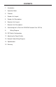
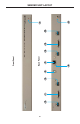
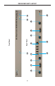
2 3 4 5 4 6 7 Back Panel Front Panel 8 9 10 11 1 SENDER UNIT LAYOUT
SENDER UNIT DESCRIPTIONS 1 Power This LED indicator will glow bright red once the included 5V DC locking power supply is properly connected between the unit and an available electrical outlet. 2 CAT-6 / Link 1.1 Connect a CAT-6a cable between this port and the CAT-6 / Link 1.1 port on the Receiver unit. 3 DVI In 1 Connect a dual-link cable from this connector to the DVI (digital only) source. 4 CAT-6 / Link 1.2 Connect a CAT-6a cable between this port and the CAT-6 / Link 1.
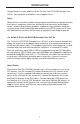
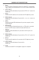
4 5 6 7 6 8 1 9 10 Back Panel Front Panel 11 12 13 2 14 3 RECEIVER UNIT LAYOUT
RECEIVER UNIT DESCRIPTIONS 1 EQ 1 The EQ adjustment (trim pot) for DVI Out 1. Both EQ 1 and EQ 2 compensate for the extension distance and the quality/skew variances that are found in different brands of CAT-6a cables. 2 EQ 2 The EQ adjustment (trim pot) for DVI Out 2. 3 Power The LED power indicator will glow bright red once the included 5V DC power supply is properly connected between the unit and an available electrical outlet. 4 Link 2.
RECEIVER UNIT DESCRIPTIONS 13 Link 1.2 Connect a CAT-6a cable between this port and the CAT-6 / Link 1.2 2 port on the Sender unit. 14 5V DC Connect the included 5V DC power supply between this input and an open wall power socket.
CONNECTING THE 2X DUAL LINK DVIKVM EXTENDER OVER CAT-6A How to Connect the 2x Dual Link DVIKVM Extender Over CAT-6a 1. Connect the included dual-link DVI cables between the DVI outputs on each computer and the DVI In connectors on the 2x Dual Link DVIKVM Extender Over CAT-6a Sender unit. 2. Connect the included USB cable from the computer (or other USB host device) to the USB In port on the Sender unit. 3. Connect five CAT-6a cables between the Sender and Receiver units.
DIP SWITCH CONFIGURATION DIP Switch Location On the bottom of both the Sender unit and Receiver unit is a bank four (4) DIP switches. The DIP switches on the Sender unit allow the management of EDID, fiber optic extenders, and HDCP. NOTE: The DIP switches on the Receiver unit do not provide any function and are reserved for future expansion. Sender unit The four DIP switches on the bottom of the Sender unit. DIP Switch 1 - EDID Management • ON - Pass Through EDID DDC and HPD are passed through.
DIP SWITCH CONFIGURATION DIP Switch 2: +5V for Fiber Optic Extenders • ON - Enable +5V Enable +5V for DVI fiber optic extenders. • OFF (default) - Disable +5V Disable +5V for DVI fiber optic extenders. DIP Switch 3: DVI Support* DIP switch 3 is only functional when DIP switch 1 is set to OFF (Local EDID). • ON - DVI Mode If a DVI connection is used, set DIP 3 to the ON position. DVI is supported by disabling HDCP pass-through.
ADJUSTING THE SIGNAL QUALITY Adjusting the Signal Quality The 2x Dual Link DVIKVM Extender Over CAT-6a Receiver unit has two trim pots (trim potentiometers) to compensate for the extension distance and the quality/skew variances that are found in different CAT-6a cabling brands. EQ 1 adjusts the output signal for DVI Out 1 and EQ 2 adjusts the signal for DVI Out 2.
NETWORK CABLE WIRING DIAGRAM Gefen has specifically engineered products to work with the TIA/EIA-568-B specification. Please follow the table below when field terminating cable for use with Gefen products. Failure to do so may produce unexpected results and reduced performance. Pin Color 1 Orange / White 2 Orange 3 Green / White 4 Blue 5 Blue / White 6 Green 7 Brown / White 8 Brown 12345678 This product was designed for use with CAT-6a (augmented) cabling only.
SPECIFICATIONS Maximum Pixel Clock.......................................................................... 2 x 165 MHz Input Video Signal...................................................................................... 1.2V p-p Input DDC Signal................................................................................. 5V p-p (TTL) Video Input Connectors (Sender).................. (2) DVI-I, 29-pin, female (digital only) Video Output Connectors (Receiver)............
WARRANTY Gefen warrants the equipment it manufactures to be free from defects in material and workmanship. If equipment fails because of such defects and Gefen is notified within two (2) years from the date of shipment, Gefen will, at its option, repair or replace the equipment, provided that the equipment has not been subjected to mechanical, electrical, or other abuse or modifications.
Rev A1 20600 Nordhoff St., Chatsworth CA 91311 1-800-545-6900 818-772-9100 www.gefen.com Pb fax: 818-772-9120 support@gefen.