® 3GSDI to HDMI® 1.3 Scaler EXT-3GSDI-2-HDMI1.3S User Manual www.gefen.
ASKING FOR ASSISTANCE Technical Support: Telephone Fax (818) 772-9100 (800) 545-6900 (818) 772-9120 Technical Support Hours: 8:00 AM to 5:00 PM Monday thru Friday, Pacific Time Write To: Gefen, LLC. c/o Customer Service 20600 Nordhoff St Chatsworth, CA 91311 www.gefen.com support@gefen.com Notice Gefen, LLC reserves the right to make changes in the hardware, packaging, and any accompanying documentation without prior written notice. 3GSDI to HDMI 1.
CONTENTS 1 2 3 4 5 6 28-29 30 31 32 33 Introduction Operation Notes Features Panel Layout Panel Descriptions Connecting And Operating The 3G-SDI To HDMI Scaler 6 Setting up the Scaler for the First Time 7 RMT-8HDS-IR Remote Description 8 IR Remote Installation 9 RMT-8HDS-IR Remote Configuration 10 Controlling the 3GSDI to HDMI 1.
INTRODUCTION Congratulations on your purchase of the 3GSDI to HDMI 1.3 Scaler. Your complete satisfaction is very important to us. Gefen Gefen delivers innovative, progressive computer and electronics add-on solutions that harness integration, extension, distribution and conversion technologies.
OPERATION NOTES READ THESE NOTES BEFORE INSTALLING OR OPERATING THE 3GSDI TO HDMI 1.3 SCALER • The built-in GUI (Graphical User Interface) or On-Screen Display (OSD) provides convenient operation of the Scaler. The supplied IR Remote control operates the OSD. Page 10 and following cover OSD functions. • The IR Remote’s operating channel must be identical to that of the Scaler. Please see page 9 for complete details on how to configure the IR Channel. • The 3GSDI to HDMI 1.
FEATURES Features • View 3G-SDI video directly from a 3G-SDI network scaled onto any HDMIcompliant display at any resolution you choose. • 225 MHz Video Bandwidth (max. output resolution supported: 2048x1080/24) • 10-bit Deep Color (RGB & YCbCr 4:4:4 only) • Up to 8 channels of PCM audio embedded into the HDMI output signal • Dolby Digital/DTS AC3 encoded audio • Separate multi-channel S/PDIF digital audio output of converted SDI audio for amplification and/or monitoring purposes.
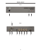
PANEL LAYOUT Front 1 2 3 4 Back 5 6 7 8 9 4 10 11 12
PANEL DESCRIPTIONS 1 IR Window (Sensor) Electronic sensor which receives IR commands from the IR Remote Control. 2 Power LED Indicator (Red) Becomes active when power is supplied to the Scaler via the included 5V power adapter. Also indicates when there is an error with the Scaler. If the Scaler encounters an error that it cannot fix, it will blink the power LED (please see the Troubleshooting section for further information on page 25).
CONNECTING AND OPERATING THE 3GSDI TO HDMI 1.3 SCALER Setting up the Scaler for the First Time 1. Connect the SD/HD/3G-SDI source(s) to the SDI input(s) on the Scaler. If using a dual-link SDI source, ensure that both SDI inputs 1 and 2 are connected. If SDI source monitoring is desired, connect an SDI output device on the SDI loop output. 2. SDI audio may be monitored on digital audio equipment by connecting amplification/ output devices to the S/PDIF output on the Scaler. 3.
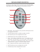
RMT-8HDS-IR REMOTE DESCRIPTION Operation of the Scaler is done by IR Remote Control (Gefen part no. EXT-RMT-8HDS-IR, provided with the 3GSDI to HDMI 1.3 Scaler). The remote control has directional buttons to navigate within the On-Screen Display (OSD) menu system that drives the Scaler. 1 2 9 3 8 4 7 5 6 1. LED indicator - lights up whenever a key is pressed, confirming transmission of IR commands to the Scaler. 2. The ENTER button activates a selected menu option in the OSD. 3.
IR REMOTE INSTALLATION 1. Remove battery cover from the back of the included RMT-SHDS-IR remote. 2. Verify that DIP switches 1 and 2 are in the down (OFF) position. (See page 9 for DIP Switch IR Channel Settings.) 3. Insert the battery, holding the battery so that you can see the positive side facing up. The side that is not marked must be facing down. 4. Test the RMT-8HDS-IR remote by pressing ONLY one button at a time. The indicator light on the remote will flash once each time you press a button.
RMT-8HDS-IR REMOTE CONFIGURATION How to Resolve IR Code Conflicts In the event that IR commands from other remote controls conflict with the supplied RMT-8HDS-IR remote control, changing the remote channel will alleviate this issue. The RMT-8HDS-IR remote control has DIP SWITCHES for configuring the remote channel. The Scaler must match the remote channel set in the RMT-8HDS-IR remote control. Please see page 18 for instructions on how to configure the channel on the Scaler.
CONNECTING AND OPERATING THE 3GSDI TO HDMI 1.3 SCALER Controlling the 3GSDI to HDMI 1.3 Scaler The 3GSDI to HDMI 1.3 Scaler has a built in GUI (Graphical User Interface) for navigating the various functions, otherwise known as the On-Screen Display or OSD. The OSD is navigated by the included IR remote control. Please see the RMT-8HDS-IR Remote Description on page 7 for functional information.
CONNECTING AND OPERATING THE 3GSDI TO HDMI 1.3 SCALER Supported Video and Graphics Formats The following table contains all supported video and graphic formats for the Gefen 3GSDI to HDMI 1.3 Scaler. The Scaler can receive any of the input formats and can convert these to any of the output formats listed. Formats not listed in the following table are not supported by this device.
CONNECTING AND OPERATING THE 3GSDI TO HDMI 1.3 SCALER Supported Video & Graphic Formats, Continued Format Mode Signal Type 1920x1080 24 PsF 1920x1080 23.98 P 1920x1080 23.98 PsF 2048x1080 24 P 2048x1080 24 PsF 2048x1080 23.98 P 2048x1080 23.
CONNECTING AND OPERATING THE 3GSDI TO HDMI 1.3 SCALER Utilizing the On-Screen Display (OSD) Menu To access the 3GSDI to HDMI 1.3 Scaler OSD menu, it must be connected to an HDMIcompliant video display device using an HDMI cable. Push the MENU button on the IR Remote to make the OSD menu appear or disappear. When first activated, the initial OSD screen shows the software revision and the remote channel number.
CONNECTING AND OPERATING THE 3GSDI TO HDMI 1.3 SCALER Patterns The 3GSDI to HDMI 1.3 Scaler has 2 built-in test patterns: Color Bars and Cross Hatch, useful for testing the device and calibrating the settings. Figure 4 - Patterns Color Bars & Cross Hatch Test Patterns Activates the two test patterns (see menu above).
CONNECTING AND OPERATING THE 3GSDI TO HDMI 1.3 SCALER Output Formats Menu The video signal created on the HDMI output port can be configured from the Output menu. The user can select Video (TV), Graphic (computer) or custom output format. The output color space, the frame rate and Deep Color settings can also be configured. Figure 7 - Output Available Formats / Monitor Supported Feature By default all options are selected, allowing selection of any output format.
CONNECTING AND OPERATING THE 3GSDI TO HDMI 1.3 SCALER Video Output Formats This section of the menu contains all video formats that can be output by the scaler on the HDMI output. If the Monitor Supported option is selected (see Available Formats), some formats will be disabled. If the current output format is a video format, a check mark will be visible on the “Video Output Format” box (please see figure below).
CONNECTING AND OPERATING THE 3GSDI TO HDMI 1.3 SCALER Custom Output Format This function allows creation of a custom output. 720p is the default. Check the specifications of your output device to ensure compatibility when creating a custom output format. Figure 11 - Custom Output Format HDMI Output Link Configuration You can select the color space of the HDMI output here.
CONNECTING AND OPERATING THE 3GSDI TO HDMI 1.3 SCALER Deep Color The Gefen 3GSDI to HDMI 1.3 Scaler supports Deep Color at 10 bits in the 4:4:4 configurations. Deep Color can be set to Automatic or Forced to 8 bits. The 8-bit option disables the transmission of Deep Color packets. The automatic option will transmit in deep color whenever possible, according to the EDID information of the monitor. To be able to output HDMI 1.
CONNECTING AND OPERATING THE 3GSDI TO HDMI 1.3 SCALER SDI Input Format When the Scaler sees a valid SD/HD/3G-SDI source as input, the format is displayed at the bottom of the OSD and checked in the menu choices. “Auto detect” appears if no valid input is found. In such cases, the Scaler can be set to use a specific format. To do so, set the link configuration first (see below) to avoid mistakes such as confusing dual link resolution with single link (as in 1080p).
CONNECTING AND OPERATING THE 3GSDI TO HDMI 1.3 SCALER Clean Aperture The clean aperture size and position can be configured. You can set the percentage (as a function of the production aperture) of the signal that is active. By default the horizontal and vertical size is set to 100% and centered at 50, 50 as the horizontal and vertical position. Note that if no video signal input is detected this menu is disabled. Figure 18 - Clean Aperture Film Mode The film mode feature can be enabled or disabled.
CONNECTING AND OPERATING THE 3GSDI TO HDMI 1.3 SCALER SDI Audio Channel This menu selects the number of audio channel(s) to be extracted from the SDI video input. Figure 20 - Audio IR Remote Channel The Scaler’s IR remote control transmits IR codes on a single infrared channel. A total of four (4) channels are available for use by the Scaler and its IR Remote.
CONNECTING AND OPERATING THE 3GSDI TO HDMI 1.3 SCALER Picture Adjustment/Enhancement Functions The Scaler’s operating functions can be adjusted to produce the best output picture possible with the connected equipment. The following submenus in the OSD will outline these capabilities: Figure 22 - Picture Adjustments Color Brightness & Contrast Adjustments The brightness and contrast can be adjusted for each primary color (red, green and blue). The default is 50 with a range of 0 to 100.
CONNECTING AND OPERATING THE 3GSDI TO HDMI 1.3 SCALER Gamma Correction Gamma correction and the gamma coefficient may be adjusted in this screen of the OSD menu system. Figure 24 - Gamma Correction Two predefined tables are available: Default and sRGB. The user can also define a custom User Table by using commands sent over the USB port via the downloaded software from Gefen (see Appendix B, p. 27).
CONNECTING AND OPERATING THE 3GSDI TO HDMI 1.3 SCALER Noise Reduction Control The level of digital noise reduction can be configured as a percentage from 0 to 100. The default value is 0; the maximum value is 100. Figure 26 - Noise Reduction Motion Threshold Control The motion threshold can be set from 0 to 15. The default value is 4.0.
CONNECTING AND OPERATING THE 3GSDI TO HDMI 1.3 SCALER Output Color Range The RGB output color range may be changed/set from limited (16-235) to full (0-255). The output link configuration must be set to RGB 4:4:4 otherwise this menu is disabled. SDI values ranging from 16-235 will be scaled to 0-255. Figure 28 - Output Color Range Layout Menu Leads to deeper menus covered on the next page featuring adjustment of the picture size, aspect ratio, and more.
CONNECTING AND OPERATING THE 3GSDI TO HDMI 1.3 SCALER Size & Position of the Output Picture The size and position of the HDMI output picture can be changed. By default, the horizontal and vertical dimensions fully match the output dimensions. For example, an output format of 720p will have a horizontal size of 1280 and a vertical size of 720 (see Figure 30 below). These values may be decreased to reduce the size of the output picture, after which it may be moved horizontally or vertically.
CONNECTING AND OPERATING THE 3GSDI TO HDMI 1.3 SCALER Extracting a Subset of the Source Signal The Extract command takes a subset (cropping) of the SD/HD/3G-SDI source picture and replicates that portion only to the HDMI output device. The extraction size (crop size) can be selected in the OSD menu. By default 100% of the picture is extracted. Figure 33 - Through (No Scaling) Through Mode The Through mode does not resize or scale the picture.
TROUBLESHOOTING Troubleshooting Tips The power LED is continuously blinking. • First, disconnect all input and output A/V devices from the Scaler, then reset it by removing the power for several seconds. If the problem persists, try performing a software upgrade (see Appendix A, page 27). • Note that the power LED blinks when it receives an infrared signal. This is normal behavior that happens when a button is pressed on the IR Remote.
TROUBLESHOOTING Troubleshooting Tips, Continued Deep color is not working. • Does the display device on the HDMI output support HDMI 1.3 and Deep Color? • Make sure the output link configuration is not set to YCbCr 4:2:2, since YCbCr 4:2:2 does not support Deep Color. In the OSD, set the link configuration in the output menu to RGB 4:4:4. Also try YCbCr 4:4:4. The Scaler is not responding to the IR remote control commands.
APPENDIX A: SOFTWARE UPDATES Installing Software Updates from Gefen Periodic software updates will fix known technical issues and enhance capabilities. Updates are done with a PC running Microsoft Windows XP® or Windows Vista® and either one of an available Serial port or USB port, depending on what is most convenient. A DB9 serial cable is included with the Scaler. Software upgrades are found at Gefen’s website in the Support/Downloads section.
APPENDIX B: GAMMA USER TABLE UPDATES Programming the Gamma User Table The Gamma Look Up Table (LUT) can be programmed using the GefenUpdater. exe utility program used to perform software updates. To do this, first prepare a CSV data file with the extension .csv (see the CSV file / LUT file format definition immediately below). When the CSV file is ready, create a batch file in Microsoft Notepad with a single line in it as follows: “GefenUpdater GAMMA FileName.csv”. Save the file as “UpdateGamma.bat”.
SPECIFICATIONS Max. image output resolution ......................................................... 2048x1080p24 Input A/V Bandwidth ........................................ Up to 2 x 2.97 Gbps (Two 3G-SDI) Output A/V Bandwidth ........................................ 225 MHz (Single Link HDMI 1.3) A/V Input Connector ......................................................... (2) BNC female 3G-SDI A/V Output Connector ......................................................
WARRANTY Gefen warrants the equipment it manufactures to be free from defects in material and workmanship. If equipment fails because of such defects and Gefen is notified within two (2) years from the date of shipment, Gefen will, at its option, repair or replace the equipment, provided that the equipment has not been subjected to mechanical, electrical, or other abuse or modifications.
Rev B5 20600 Nordhoff St., Chatsworth CA 91311 1-800-545-6900 818-772-9100 www.gefen.com Pb This product uses UL listed power supplies. fax: 818-772-9120 support@gefen.