
User manual


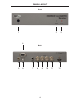


1 IR Window (Sensor)
Electronic sensor which receives IR commands from the IR Remote Control.
2 Power LED Indicator (Red)
Becomes active when power is supplied to the Scaler via the included 5V power
adapter. Also indicates when there is an error with the Scaler. If the Scaler
encounters an error that it cannot fi x, it will blink the power LED (please see the
Troubleshooting section for further information on page 25).
3 3G LED Indicator (Blue)
Lights up when input to the Scaler is a 3G-SDI signal.
4 RS-232 Serial Port
This port is used to control the Scaler using RS-232. A DB9 serial cable is
provided for this purpose.
5 5V Locking Power Input Connector
Plug the included power supply’s threaded power connector into this terminal
and screw it in fi rmly, then plug in the wall adapter.
6 USB 2.0 Input Port
This high-speed input port is used to update the internal software of the Scaler
(see page 27). The user must supply a USB cable to utilize this port.
7 S/PDIF Coaxial Digital Audio Ouput
Outputs up to 5.1 channels of digital audio extracted from the HDMI source to a
S/PDIF coaxial digital output for monitoring and/or external amplifi cation.
8 SD/HD/3G-SDI Input 1
Receives incoming SDI source signal No. 1.
9 SD/HD/3G-SDI Loop Output 1
Allows monitoring of SDI source signal No. 1 (no scaling is performed).
10 SD/HD/3G-SDI Input 2
Receives incoming SDI source signal No. 2 (no input selection is allowed).
11 SD/HD/3G-SDI Loop Output 2
Allows monitoring of SDI source signal No. 2 before conversion to HDMI takes
place (no scaling is performed).
12 HDMI Output
Sends converted SD/HD/3G-SDI to an HDMI display/output device.
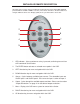
PANEL DESCRIPTIONS
5