
User manual


5
M
ODULE DESCRIPTION
S
1
3
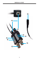
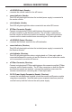
G-SDI BNC Input
(
Sender
)
C
onnects the
S
ender module to the
S
DI source.
2
P
ower Indicator
(
Sender
)
This LED will
g
low bri
g
ht red when the included power suppl
y
is connected to
the
S
ender module.
3
L
ink Indicator
(
Sender
)
This LED will
g
low bri
g
ht blue when connected to an active
S
DI source.
4
S
T-Fiber Connector
(
Sender
)
C
onnect a sin
g
le-strand
S
T-
fi
ber cable between this connector and th
e
S
T-
fi
ber connector on the Receiver module. The
S
T Fiber
C
onnectors o
n
both the
S
ender and Receiver module are identical. Remove the protective
c
overs
f
rom the
S
ender module be
f
ore connectin
g
the
S
T
fi
ber optic cable.
5
3
G-SDI BNC Output
(
Receiver
)
C
onnects the Receiver module to the
S
DI destination.
6
P
ower Indicator
(
Receiver
)
This LED will
g
low bri
g
ht red when the included power suppl
y
is connected to
th
e
R
ece
iv
e
r m
odu
l
e
.
7
L
ink Indicator
(
Receiver
)
This LED will
g
low bri
g
ht blue when a sin
g
le-strand o
f
S
T-
fi
ber optic cable is
c
onnected between the
S
ender unit and the Receiver unit and when the
S
ender
u
nit is connected to an active
S
DI source.
8
S
T-Fiber Connector
(
Receiver
)
C
onnect a sin
g
le-strand
S
T-
fi
ber cable between this connector and the
S
T-
fi
ber
c
onnector on the
S
ender module. The
S
T-
fi
ber connectors on both the
S
ender
a
n
d
R
ece
iv
e
r m
odu
l
e
a
r
e
i
de
nti
ca
l.
R
emove the protective covers
f
rom the
R
eceiver module be
f
ore connectin
g
the
S
T
fi
ber optic cable.
9
5V DC Power Supply Receptacle (Sender / Receiver)
C
onnect the included power supplies to both the
S
ender and Receiver module
u
sin
g
these receptacles. Note that each power receptacle has three pins that
m
ust be lined up with the holes on the each power suppl
y
.