® A/V Conference Room Processor EXT-AVCONFS User Manual www.gefen.
ASKING FOR ASSISTANCE Technical Support: Telephone Fax (818) 772-9100 (800) 545-6900 (818) 772-9120 Technical Support Hours: 8:00 AM to 5:00 PM Monday thru Friday Pacific Time Write To: Gefen, LLC c/o Customer Service 20600 Nordhoff St Chatsworth, CA 91311 www.gefen.com support@gefen.com Notice Gefen, LLC reserves the right to make changes in the hardware, packaging and any accompanying documentation without prior written notice.
CONTENTS 1 Introduction 2 Operation Notes 3 Features 4 Front Panel Layout 5 6 7 8 9 Front Panel Descriptions Back Panel Layout Back Panel Descriptions Front Panel Button Layout Front Panel Button Descriptions 10 IR Remote Control Layout 11 IR Remote Control Descriptions 12 Installing the IR Remote Control Unit 13 IR Remote Control Unit Configuration 14 Connecting the A/V Conference Room Processor 15 Wiring Diagram 16 Front Panel 19 Menu System 27 RS-232 Serial Commands 27 Audio Commands
INTRODUCTION Congratulations on your purchase of the A/V Conference Room Processor. Your complete satisfaction is very important to us. Gefen Gefen delivers innovative, progressive computer and electronics add-on solutions that harness integration, extension, distribution and conversion technologies.
OPERATION NOTES PLEASE READ THESE NOTES BEFORE INSTALLING OR OPERATING THE A/V CONFERENCE ROOM PROCESSOR • The A/V Conference Room Processor has three (3) separate RCA outputs which are intended to be used with a separate audio amplifier. Up to six channels of audio can be down-mixed to left, right, and subwoofer. • This unit will support the following audio formats: LPCM (up to 6 channels) Dolby Digital (AC-3 up to 6 channels) • This unit will accept sources that use Deep Color.
FEATURES Features • Scales and outputs resolutions up to 1080p, 2K, and 1920x1200 • Switches and converts various A/V sources to HDMI • Dolby Digital™ decoding and processing • Advanced EDID Management • High performance frame rate conversion engine • Auto 3:2 pull-down and 2:2 pull-down detection and recovery • Aspect Ratio Control • Built-in menu system • RS-232 Control • Field upgradable firmware • Rack-mountable (rack ears included) Package Includes • • • • • (1) A/V Conference Ro
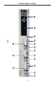
1 3 2 4 5 7 6 8 9 11 10 12 Front 13 14 15 FRONT PANEL LAYOUT 4
FRONT PANEL DESCRIPTIONS 1 Analog L/R (RCA) Input Connect a L/R RCA stereo pair from the Component 1 source to this input. 2 S/PDIF Input Connect a Coax cable, as part of the Component 1 source, to this input. 3 TOSLINK Input Connect an Optical cable, as part of the Component 1 source, to this input. 4 Component 1 Input Connect the red, green, and blue cables from the Component 1 video source to these inputs.
1 2 3 4 5 7 6 8 9 Back 10 11 12 13 BACK PANEL LAYOUT 6
BACK PANEL DESCRIPTIONS 1 HDMI Output Connect an HDMI cable from the A/V Conference Room Processor to an HDTV display. 2 Analog L/R (RCA) Input Connect a L/R RCA stereo pair from the Component 2 source to this input. 3 S/PDIF Input Connect a Coax cable, as part of the Component 2 source, to this input. 4 Component 2 Input Connect the red, green, and blue cables from the Component 2 video source to these inputs.
FRONT PANEL BUTTON LAYOUT The A/V Conference Room Processor uses a series of push buttons, located on the front panel, for all input selection and feature functions. All status information, such as the input and output resolutions are always available on the front panel LCD Screen. User adjustable features, such as color correction and aspect ratio, can be navigated and adjusted by referencing either the LCD Screen or the OnScreen Display (OSD).
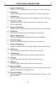
FRONT PANEL BUTTON DESCRIPTIONS 1 Left Cursor Button This button is used to navigate the Menu System and change settings by moving the cursor to the left. 2 Up Button This button is used to navigate the Menu System and change settings by moving the cursor up. This button is also used for increasing the audio volume in the Status Screen (see page 17). 3 Down Button This button is used to navigate the Menu System and change settings by moving the cursor down.
IR REMOTE CONTROL LAYOUT 17 15 1 11 2 10 16 12 14 13 3 9 4 5 8 6 7 1 Mute Button Enables / disables muting of the audio output signal. 2 Video Format Button Cycles through the available output resolutions. See page 22 for a list of the available Output Resolutions. 3 Pict Mode Button Cycles through the different picture modes (Standard, Movie, Vivid, and User). See page 19 for details. 4 DVI 1 2 Button Toggles between the DVI 1 and DVI 2 A/V inputs.
IR REMOTE CONTROL DESCRIPTIONS 7 Audio Input Button Cycles between the available audio inputs for the selected video input. 8 PC VGA Selects the VGA video input. 9 Exit Button Exits a menu or sub-menu within the built-in menu system. 10 Menu Button Places the Conference Room Processor in Menu Mode, allowing adjustment of scaling, color correction, and other features. 11 Power Button Used to turn on or turn off the Conference Room Processor.
INSTALLING THE IR REMOTE CONTROL UNIT Installing the Battery 1. Remove the battery cover on the back of the IR Remote Control unit. 2. Insert the included battery into the open battery slot. The positive (+) side of the battery should be facing up. 3. Replace the battery cover. The Remote Control unit ships with two batteries. One battery is required for operation and the other battery is a spare. Battery Slot CAUTION: Risk of explosion if battery is replaced by an incorrect type.
IR REMOTE CONTROL UNIT CONFIGURATION Setting the IR Remote Control Channel In the event that IR commands from other remote controls interfere with the supplied IR Remote Control unit, changing the IR Remote Control’s IR channel will fix the problem. The IR Remote Control unit has a bank of DIP switches used for setting the IR channel. The DIP switch bank is located underneath the battery cover.
CONNECTING THE A/V CONFERENCE ROOM PROCESSOR How to Connect the A/V Conference Room Processor 1. 2. Connect video source devices to the A/V Conference Room Processor video inputs. The following inputs are available: Front Panel Back Panel HDMI N/A DVI-I (analog and digital DVI) DVI-D (digital DVI) VGA N/A Component Component Connect audio sources to the A/V Conference Room Processor audio inputs.
CONNECTING THE A/V CONFERENCE ROOM PROCESSOR Wiring Diagram for the A/V Conference Room Processor SUBWOOFER AUDIO (RCA) CABLE DVI Source DVI / HDMI Source DIGITAL AUDIO (TOSLINK) DIGITAL AUDIO (COAX) ANALOG AUDIO (RCA) COMPONENT SPEAKER CABLE CABLE CABLE CABLE CABLE RS-232 HDMI VGA DVI CABLE CABLE CABLE CABLE Component Source VGA Source Component Source Speaker Speaker Subwoofer HDMI Display RS-232 RS 232 Controller C t ll Audio Receiver EXT-AVCONFS ATTENTION: This product should always be co
FRONT PANEL Status Screen The Status Screen displays information regarding the current settings of the Audio Processor. The Status Screen is also used in conjunction with navigating the built-in Menu System.
FRONT PANEL Adjusting the Volume Use the Up Button and Down Button to increase or decrease the audio gain in the Status Screen. Audio gain can be reduced to a minimum of -60 dB and to a maximum of +10 dB. Each time these buttons are pressed, the volume is increased or decreased by 1 dB. To increase or decrease the audio gain at a faster rate, press and hold down either of these buttons until the desired volume is achieved.
FRONT PANEL Firmware Version To display the firmware version of the A/V Conference Room Processor, press either the ◄ or ► buttons on the front panel: Pressing the ◄ or ► will cycle between the Firmware Version screen and the information on the Status Screen. Selecting the Input Source Use the buttons on the front panel to select the input source.
MENU SYSTEM Video Menu To access the Video Menu, press the Menu button on the front panel. Use the ▼ or ▲ buttons to highlight the Video Menu icon. Press the Menu button to enter the Video Menu. Use the ▼ or ▲ buttons to scroll through each of the parameters. Press the Menu button to change the selected parameter. Use the ◄ or ► buttons to increase or decrease the values. Picture Mode Preset and user configuration settings for different viewing scenarios. Preset settings will not allow user adjustment.
MENU SYSTEM Scale Sets the scaling adjustment. Options are: Full, Overscan, Underscan, Letterbox U.S. (Underscan), PanScan U.S. (Underscan), Letterbox Full, and PanScan Full. • Full Stretches the image to fill the screen • Overscan Stretches the image to fullscreen and just beyond the border of the display • Underscan Stretches the image to fullscreen and just within the border of the screen • Letterbox U.S. (Underscan) Stretches the image to 16:9 aspect ratio with underscan • PanScan U.S.
MENU SYSTEM Color Menu To access the Output Menu, press the Menu button. Use the ▼ or ▲ buttons to highlight the Output Menu icon. Press the Menu button to enter the Output Menu. Use any of the arrow buttons on the front panel to select the desired output resolution. Press the Enter button to enable the selected output resolution. Select the Exit option to exit the Color Menu and return control to the Main Menu. Color Tone • Normal Use for general content.
MENU SYSTEM Output Menu To access the Output Menu, press the Menu button. Use the ▼ or ▲ buttons to highlight the Output Menu icon. Press the Menu button to enter the Output Menu. Use any of the arrow buttons on the front panel to select the desired output resolution. Press the Enter button to enable the selected output resolution. Select the Exit option to exit the Color Menu and return control to the Main Menu.
MENU SYSTEM OSD Menu To access the OSD Menu, press the Menu button. Use the ▼ or ▲ buttons to highlight the OSD Menu icon. Press the Menu button to enter the OSD Menu. Use the ◄ or ► buttons to select the desired output resolution. Press the Enter button to enable the selected output resolution. Use the ◄ or ► buttons to select the Exit option to exit the Speaker Menu and return control to the Main Menu. H-Position (Horizontal Position) Adjusts the horizontal position on the Menu System on the screen.
MENU SYSTEM Audio Menu To access the Audio Menu, press the Menu button. Use the ▼ or ▲ buttons to highlight the Audio Menu icon. Press the Menu button to enter the Audio Menu. Use the + or - buttons to select the desired output resolution. Press the Enter button to enable the selected output resolution. Use the + or - buttons to select the Exit option to exit the Audio Menu and return control to the Main Menu. DVI1 Selects the audio input for DVI In 1. Options are: Analog, S/PDIF, or TOSLINK.
MENU SYSTEM Speakers Menu To access the Speakers Menu, press the Menu button. Use the ▼ or ▲ buttons to highlight the Speakers Menu icon. Press the Menu button to enter the Speaker Menu. Use the ◄ or ► buttons to select the desired option. Use the + or - buttons to select the Exit option to exit the Speaker Menu and return control to the Main Menu. Size Selects the size of the speakers (left / right). Options are: Large or Small. Subwoofer Selects the presence or absence of the subwoofer.
MENU SYSTEM Level Sub Sets the offset volume level for the left speaker. Minimum value: +0 dB, Maximum value: +10 dB Exit Exits the Speaker Menu and returns control to the Main Menu.
RS-232 SERIAL COMMANDS 54321 12345 9876 6789 Only Pins 2 (RX), 3 (TX), and 5 (Ground) are used on the RS-232 serial interface RS232 Settings Bits per second ............................................................................................ 19200 Data bits ............................................................................................................... 8 Parity .............................................................................................................
RS-232 SERIAL COMMANDS Command Syntax The syntax for each command is as follows: CommandName [space] param1 [space] param2...paramN \r The command syntax is NOT case sensitive. ADELAY Command The ADELAY command sets the audio delay. Syntax: ADELAY param1 Parameters: param1 Value Value Meaning Off Audio delay off 40 40 ms delay 110 110 ms delay 150 150 ms delay Notes: Use ? for param1 to retrieve the current value.
RS-232 SERIAL COMMANDS AENHNCE Command The AENHNCE command improves the speech intelligibility. Syntax: AENHNCE param1 Parameters: param1 Mode Mode Meaning Off Enhance mode off Night Low volume for night viewing Voice Dialog becomes more clear Volume Emphasized audio gain Notes: Use ? for param1 to retrieve the current value. AIN Command The AIN command set the audio input source.
RS-232 SERIAL COMMANDS BASS Command The BASS command sets the bass level. Syntax: BASS param1 Parameters: param1 Level [-12 ...12] Notes: The + or - character can also be used, instead of specifying a value, in order to increase or decrease the bass level by 1 dB. Use ? for param1 to retrieve the current value.
RS-232 SERIAL COMMANDS DFR Command The DFL command sets the distance of the Front Right speaker. Syntax: DFR param1 Parameters: param1 Level [0 ...10] Notes: The + or - character can also be used, instead of specifying a value, in order to increase or decrease the Front Right distance by 1 foot intervals. Use ? for param1 to retrieve the current value. DRC Command The DRC command adjusts the Dynamic Range Control.
RS-232 SERIAL COMMANDS DSB Command The DSB sets the distance of the Subwoofer. Syntax: DSB param1 Parameters: param1 Level [0 ...10] Notes: The + or - character can also be used, instead of specifying a value, in order to increase or decrease the Subwoofer distance by 1 foot intervals. Use ? for param1 to retrieve the current value. FLR Command The FLR command sets the size of the Front Left and Front Right speakers.
RS-232 SERIAL COMMANDS LFV Command The LFV command sets the Front Left speaker volume. Syntax: LFV param1 Parameters: param1 Level [-10...10] Notes: The + or - character can also be used, instead of specifying a value, in order to increase or decrease the Front Left speaker volume by 1 dB intervals. Use ? for param1 to retrieve the current value. MUTE Command The MUTE command enables or disables audio muting.
RS-232 SERIAL COMMANDS RTV Command The RTV command sets the Front Right speaker volume. Syntax: RTV param1 Parameters: param1 Level [-10...10] Notes: The + or - character can also be used, instead of specifying a value, in order to increase or decrease the Front Right speaker volume by 1 dB intervals. Use ? for param1 to retrieve the current value. SUB Command The SUB command enables or disables the subwoofer. If a subwoofer is not connected, the subwoofer should be disabled.
RS-232 SERIAL COMMANDS SUBV Command The SUBV command sets the subwoofer volume. Syntax: SUBV param1 Parameters: param1 Level [-10...10] Notes: The + or - character can also be used, instead of specifying a value, in order to increase or decrease the subwoofer volume by 1 dB intervals. Notes: Use ? for param1 to retrieve the current value. SUBX Command The SUBX command adjusts the crossover frequency.
RS-232 SERIAL COMMANDS TREB Command The TREB command sets the treble subwoofer volume. Syntax: TREB param1 Parameters: param1 Level [-12...12] Notes: The + or - character can also be used, instead of specifying a value, in order to increase or decrease the treble level by 1 dB intervals. Use ? for param1 to retrieve the current value. VOL Command The VOL sets the overall output audio signal. Syntax: VOL param1 Parameters: param1 Value [-81...
RS-232 SERIAL COMMANDS General Commands Command Description IR Sets the IR channel OSDHPOS Sets the horizontal position of the OSD OSDVPOS Sets the vertical position of the OSD POWER Turns the Scaler ON or OFF IR Command The IR command sets the IR Channel used by the Scaler. The IR channel can be set to 1, 2, 3, or 4. Syntax: IR param1 Parameters: param1 Level [1...4] Notes: Set param1 to ALL to have the Scaler receive on any IR channel. Use ? for param1 to retrieve the current value.
RS-232 SERIAL COMMANDS OSDVPOS Command The OSDVPOS command sets the vertical position of the OSD. Syntax: OSDVPOS param1 Parameters: param1 VPos [0...100] Notes: Use ? for param1 to retrieve the current value. POWER Command The POWER command turns the Scaler ON or OFF. Syntax: OSDVPOS param1 Parameters: param1 State Value Meaning Off Power Off On Power On TGL Toggle Power State Notes: Setting param1 to TGL will automatically toggle the current power state.
RS-232 SERIAL COMMANDS Video Commands Command Description BLUE Set the blue color component value BRTNESS Sets the brightness value CLRTMP Sets the color temperature CONTRST Sets the contrast level GREEN Sets the green color component value HUE Sets the hue NR Sets the noise reduction level OUT Sets the output resolution PCHPOS Adjusts the horizontal position of the output signal PCVPOS Adjusts the vertical position of the output signal PMODE Sets the picture mode RED Sets the red c
RS-232 SERIAL COMMANDS BRTNESS Command The BRTNESS sets the brightness level of the output. Syntax: BRTNESS param1 Parameters: param1 Value [0...100] Notes: The + or - character can also be used, in place of specifying a value, to increase or decrease the brightness value by intervals of 1. Use ? for param1 to retrieve the current value. CLRTMP Command The CLRTMP command sets the color temperature.
RS-232 SERIAL COMMANDS CONTRST Command The CONTRST sets the contrast level on the output signal. Syntax: CONTRST param1 Parameters: param1 Value [0...100] Notes: The + or - character can also be used, in place of specifying a value, to increase or decrease the contrast value by intervals of 1. Use ? for param1 to retrieve the current value. GREEN Command The GREEN command sets the green color component value. Syntax: GREEN param1 Parameters: param1 Value [0...
RS-232 SERIAL COMMANDS HUE Command The HUE sets the color hue level. Syntax: HUE param1 Parameters: param1 Value [0...100] Notes: The + or - character can also be used, in place of specifying a value, to increase or decrease the color hue by intervals of 1. Use ? for param1 to retrieve the current value. NR Command The NR command sets the noise reduction value.
RS-232 SERIAL COMMANDS OUT Command The OUT command sets the output resolution.
RS-232 SERIAL COMMANDS PCHPOS Command The PCHPOS command sets the horizontal position of the output signal on the display. Syntax: PCHPOS param1 Parameters: param1 Value [0...100] Notes: The + or - character can also be used, in place of specifying a value, to move the picture right (+) or left (-) by intervals of 1. Use ? for param1 to retrieve the current value. \PCVPOS Command The PCVPOS command sets the vertical position of the output signal on the display.
RS-232 SERIAL COMMANDS PMODE Command The PMODE command loads a predefined color and brightness calibration which is applied to the output signal. Syntax: PMODE param1 Parameters: param1 Mode Mode Meaning std Standard picture mode mov Movie mode vivd Vivid colors mode user User defined Notes: Use ? for param1 to retrieve the current value. RED Command The RED command sets the green color component value. Syntax: RED param1 Parameters: param1 Value [0...
RS-232 SERIAL COMMANDS SATURTN Command The SATURTN command sets the saturation level of the output signal. Syntax: SATURTN param1 Parameters: param1 Value [0...100] Notes: The + or - character can also be used, in place of specifying a value, to increase or decrease the saturation value by intervals of 1. Use ? for param1 to retrieve the current value. SHARP Command The SHARP command sets the sharpness level. Syntax: SHARP param1 Parameters: param1 Value [0...
RS-232 SERIAL COMMANDS SIZE Command The SIZE command sets the saturation level of the output signal. Syntax: SIZE param1 Parameters: param1 Size Size Meaning full Full-screen picture mode ovscan Overscan mode unscan Underscan mode ltrbox Letterbox mode (16:9) pnscan Pan-and-Scan (4:3) Notes: Use ? for param1 to retrieve the current value. VIN Command The VIN command sets the active video input source.
MAIN MENU SYSTEM SUMMARY Menu ▲ ▲ Exit ▲ ▲ Exit ▲ ▲ Exit ▲ ▲ Exit ▲ ▲ Exit ▲ Exit ▲ 48
VIDEO MENU SUMMARY Status Screen ▲ ▲ Exit Exit ▲ ▲ ▲ Standard Movie Vivid ▲ User ▲ ▲ Exit ▲ Min: 0 Max: 100 ▲ ▲ ▲ Exit ▲ Min: 0 Max: 100 49
VIDEO MENU SUMMARY ▲ Exit ▲ ▲ Min: 0 ▲ Max: 100 ▲ ▲ ▲ Exit Min: 0 ▲ Max: 100 ▲ ▲ ▲ Exit Min: 0 ▲ Max: 100 50
VIDEO MENU SUMMARY ▲ Exit ▲ ▲ Full ▲ Overscan Underscan LetterboxUS PanScan U.S.
COLOR MENU SUMMARY Status Screen ▲ ▲ Exit Exit ▲ ▲ ▲ User Normal Warm ▲ Cool ▲ ▲ Exit ▲ Min: 0 Max: 100 ▲ ▲ ▲ Exit ▲ Min: 0 Max: 100 52
COLOR MENU SUMMARY ▲ ▲ ▲ Exit Min: 0 ▲ Max: 100 ▲ ▲ Exit 53
OUTPUT MENU SUMMARY Status Screen ▲ ▲ Exit Exit ▲ ▲ ▲ VGA ▲ SVGA Menu 54 576p XGA 720p50 SXGA 1080i50 UXGA 1080p50 1080p-1 1080p-3 480i NATIVE 480p WXGA 720p60 WSXGA 1080i60 WUXGA 1080p60 2K 1080p-2 EXIT 576i
OSD MENU SUMMARY Status Screen ▲ ▲ Exit ▲ ▲ Exit ▲ Min: 0 Max: 100 ▲ ▲ ▲ Exit ▲ Min: 0 Max: 100 ▲ 55
OSD MENU SUMMARY ▲ Exit ▲ ▲ ▲ Min: 0 Max: 100 ▲ Exit ▲ ▲ ▲ Min: 0 Max: 100 ▲ ▲ ▲ Exit ▲ 1 2 3 4 56
OSD MENU SUMMARY ▲ ▲ Exit 57
AUDIO MENU SUMMARY Status Screen ▲ ▲ Exit Exit ▲ ▲ ▲ TOSLINK Analog SPDIF ▲ ▲ ▲ Exit ▲ TOSLINK Analog SPDIF ▲ ▲ ▲ Exit ▲ TOSLINK Analog SPDIF 58
AUDIO MENU SUMMARY ▲ ▲ ▲ Exit ▲ TOSLINK Analog S/PDIF ▲ ▲ ▲ Exit ▲ S/PDIF Analog ▲ ▲ ▲ Exit ▲ Min: -12DB Max: +12DB 59
AUDIO MENU SUMMARY ▲ ▲ ▲ Exit ▲ Min: -12 dB Max: +12 dB ▲ ▲ ▲ Exit ▲ On Off ▲ ▲ ▲ Exit ▲ Volume Off Night Voice 60
AUDIO MENU SUMMARY ▲ ▲ ▲ Exit ▲ Off 40 ms 110 ms ▲ 150 ms ▲ ▲ Exit ▲ Mute ▲ ▲ On Exit 61
SPEAKER MENU SUMMARY Status Screen ▲ ▲ Exit Exit ▲ ▲ ▲ Large Small ▲ ▲ ▲ Exit ▲ On Off ▲ ▲ ▲ Exit ▲ 50 Hz 60 Hz 90 Hz 62
SPEAKER MENU SUMMARY ▲ ▲ ▲ Exit Pre-Amp ▲ Fixed ▲ ▲ ▲ Exit Min: 0 m ▲ Max: 10 m ▲ ▲ ▲ Exit Min: 0 m ▲ Max: 10 m 63
SPEAKER MENU SUMMARY ▲ ▲ ▲ Exit Min: 0 m ▲ Max: 10 m ▲ ▲ ▲ Exit Min: -10 dB ▲ Max: +10 dB ▲ ▲ ▲ Exit Min: -10 dB ▲ Max: +10 dB 64
SPEAKER MENU SUMMARY ▲ ▲ Exit 65
MOUNTING PLATE INSTALLATION Rack mount ears are provided for installation of this unit into a 2U rack mount space. 1. 2. 3. 4. Locate the side screws on the unit. Remove the front 2 screws that are located closest to the front of the unit. Using the removed screws, screw the rack mounting bracket into the unit. Repeat the procedure on the opposite side of the unit.
SPECIFICATIONS Maximum Pixel Clock................................................................................165 MHz Analog Video Bandwidth............................................................................350 MHz Input Video Signal................................................................................1.2 Volts p-p Input DDC Signal...........................................................................5 Volts p-p (TTL) HDMI Input Connector...........................................
WARRANTY Gefen warrants the equipment it manufactures to be free from defects in material and workmanship. If equipment fails because of such defects and Gefen is notified within two (2) years from the date of shipment, Gefen will, at its option, repair or replace the equipment, provided that the equipment has not been subjected to mechanical, electrical, or other abuse or modifications.
Rev A1 20600 Nordhoff St., Chatsworth CA 91311 1-800-545-6900 818-772-9100 www.gefen.com Pb This product uses UL listed power supplies. fax: 818-772-9120 support@gefen.