
User manual


7
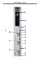
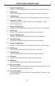
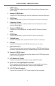
BACK PANEL DESCRIPTIONS
1 HDMI Output
Connect an HDMI cable from the A/V Conference Room Processor to an
HDTV display.
2 Analog L/R (RCA) Input
Connect a L/R RCA stereo pair from the Component 2 source to this input.
3 S/PDIF Input
Connect a Coax cable, as part of the Component 2 source, to this input.
4 Component 2 Input
Connect the red, green, and blue cables from the Component 2 video
source to these inputs.
5 Analog L/R (RCA) Input
Connect a L/R RCA stereo pair, the part of the DVI 2 source, to these
inputs.
6 S/PDIF Input
Connect a Coax cable, as part of the DVI 2 source, to this input.
7 TOSLINK Input
Connect an Optical cable, as part of the DVI 2 source, to this input.
8 DVI Input
Connect a DVI cable from the DVI 2 video source to this input.
9 RS-232 Serial Port
This port is used for serial communication using an RS-232 control device.
Access to certain features are only available through the RS-232 interface.
10 Analog L/R (RCA) Output
Connect a L/R RCA stereo pair from this output to a L/R RCA stereo input
pair on the A/V equipment.
11 LFE (Subwoofer) Output
Connect a subwoofer to this output using a single RCA cable.
12 Front Left / Front Right Speaker Terminals
These speaker binding post terminals will accept spade lug, banana
plug, dual banana plug, bare wire, and pin style connectors.
13 24 V DC Power Receptacle
Connect the included 24 V DC power supply to this receptacle.