Audio/Video Scaler Pro with Amplifier EXT-AVSCALER-PRO User Manual www.gefen.
ASKING FOR ASSISTANCE Technical Support: Telephone Fax (818) 772-9100 (800) 545-6900 (818) 772-9120 Technical Support Hours: 8:00 AM to 5:00 PM Monday thru Friday. Write To: Gefen Inc. c/o Customer Service 20600 Nordhoff St Chatsworth, CA 91311 www.gefen.com support@gefen.com Notice Gefen Inc. reserves the right to make changes in the hardware, packaging and any accompanying documentation without prior written notice. Audio/Video Scaler Pro with Amplifier is a trademark of Gefen Inc. © 2008 Gefen Inc.
CONTENTS 1 Introduction 2 Operation Notes 3 Features 4 Unit Panel Layout 5 Unit Panel Descriptions 6 Unit Panel Descriptions 7 Connecting The Audio/Video Scaler Pro with Amplifier 8 RMT-SR-IR Remote Description 9 Operating The Audio/Video Scaler Pro with Amplifier 15 RMT-SR-IR Remote Installation 16 RMT-SR-IR Code Configuration 17 RS-232 Serial Control Interface 18 Rack Mount Installation 19 Specifications 20 Warranty
INTRODUCTION Congratulations on your purchase of the Audio/Video Scaler Pro with Amplifier. Your complete satisfaction is very important to us. Gefen Gefen delivers innovative, progressive computer and electronics add-on solutions that harness integration, extension, distribution and conversion technologies.
OPERATION NOTES READ THESE NOTES BEFORE INSTALLING OR OPERATING THE AUDIO/VIDEO SCALER PRO WITH AMPLIFIER • When initially powering on HDMI or DVI-D sources, it is important to have the A/V Scaler Pro with Amplifier’s input selected to that source to ensure that the EDID (display information) is relayed properly. • Only use speakers with an impedance of 8Ω with the A/V Scaler Pro with Amplifier. • Discrete switching is available using the RS-232 serial communications port.
FEATURES Features • Both digital and analog inputs are format converted and pixel re-scaled through the Home Audio/Video Scaler Pro with Amplifier. It outputs a large range of formats and resolutions that will easily match the native resolution/ format of your display to ensure highest picture quality. • DVI/HDCP/HDMI compliant input: Operates up to 165Mhz (Up to WUXGA @60Hz) • Supports digital HD output up to 1080p • Integrated 8-bit triple-ADC/PLL. • Dual high quality scaling engines.
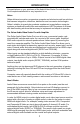
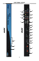
8 1 9 2 10 11 3 12 13 4 14 15 Back Panel Front Panel 16 17 18 4 19 5 20 6 7 21 UNIT PANEL LAYOUT
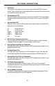
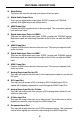
UNIT PANEL DESCRIPTIONS 1 IR Receiver This receivers will accept commands from the included RMT-SR-IR remote control. There must be line-of-sight between this receiver and the remote control for successful operation to occur. 2 Power Indicator LED This LED indicator will become active once the included 5V DC power adapter has bee properly connected between the sender unit and an open wall power socket. 3 Selected Input LED Each input source has an LED that will become active when it is selected.
UNIT PANEL DESCRIPTIONS 10 Reset Button This button will reset the unit and cycle power off and on again. 11 Digital Audio Output Ports There are two digital audio output types, S/PDIF (coaxial) and TOSLINK (optical). Both digital outputs are always active. 12 HDMI Output Port Connect the HDMI capable device to this output port. This output port supports both audio and video. 13 Digital Audio Input Ports for HDMI 2 There are two digital audio input types, S/PDIF (coaxial) and TOSLINK (optical).
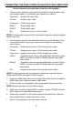
CONNECTING THE AUDIO/VIDEO SCALER PRO WITH AMPLIFIER How to Connect the Audio/Video Scaler Pro with Amplifier 1. Connect source devices to the Audio/Video Scaler Pro with Amplifier using user supplied cables. The following input options are available. Composite - Single RCA video cable. S-Video - Single s-video cable. Component - 3 RCA video cables. HDMI 1 - Single HDMI cable. HDMI 2 - Single HDMI cable. DVI - Single DVI-I, DVI-A, or DVI-D cable.
RMT-SR-IR REMOTE DESCRIPTION 1 2 3 4 5 6 7 8 9 1. Output - Cycles through hrough the available output resolutions. resolutions Please Ple see the section A/V Scaler Pro with Amplifier CONFIGURATION / Output on page 8 for the output resolution table. 2. Input - Cycles though all of input sources. The selectable inputs are Composite, S-Video, Component, HDMI 1, HDMI 2, and DVI. 3. Power - Turns the unit on and off (standby). 4. Exit - Exits the current menu option and menu system. 5.
OPERATING THE AUDIO/VIDEO SCALER PRO WITH AMPLIFIER Entering the Menu System Pressing the Menu button on the included RMT-SR-IR remote control will display the GUI (graphical user interface) for adjustment options. The GUI is overlaid onto the outgoing video to the display. Therefore, the selected source must be outputting a compatible resolution for viewing on the display. If video is not visible on the display, the GUI will also fail to be displayed. To correct this, please follow the steps below. 1.
OPERATING THE AUDIO/VIDEO SCALER PRO WITH AMPLIFIER VIDEO CONTINUED Press OK to begin adjusting settings. Use the LEFT and RIGHT buttons to change settings. Press the OK button once the desired settings are made. Contrast Adjusts the contrast in increments of 1 on a scale of 1 to 100 (default 50). Brightness Adjusts the brightness in increments of 1 on a scale of to 100 (default 50). Hue Adjusts the hue in increments of 1 on a scale of 1 to 100 (default 50).
OPERATING THE AUDIO/VIDEO SCALER PRO WITH AMPLIFIER VIDEO CONTINUED H-Pos (Horizontal Position) Adjusts the image’s horizontal position on the screen. • Adjusts in increments of 1 on a scale of 1 to 100 (default is 50) V-Pos (Vertical Position) Adjusts the image’s vertical position on the screen. • Adjusts in increments of 1 on a scale of 1 to 100 (default is 50) Y/C Separation - Only for Composite Input Selects the method in which the brightness and color are separated from the composite video signal.
OPERATING THE AUDIO/VIDEO SCALER PRO WITH AMPLIFIER COLOR Press OK to begin adjusting settings. Use the LEFT and RIGHT buttons to change settings. Press the OK button once the desired settings are made. Color Tone Sets the color for the appearance of white. Only the USER option will allow customized settings. The USER settings are saved.
OPERATING THE AUDIO/VIDEO SCALER PRO WITH AMPLIFIER OSD (ON SCREEN DISPLAY) CONTINUED Remote Channel Sets the remote channel for use with the RMT-SR-IR remote control. If the selected channel in this menu and does not match the channel set in the RMT-SR-IR remote, the unit will cease to respond to IR commands from the remote. • Selectable remote channel from 1 to 4 (default is 1) AUDIO Press OK to begin adjusting settings. Use the LEFT and RIGHT buttons to change settings.
OPERATING THE AUDIO/VIDEO SCALER PRO WITH AMPLIFIER AUDIO CONTINUED Volume Adjusts the amplified speaker output volume. The volume can also be accessed by using the UP (volume up) and DOWN (volume down) buttons on the included RMTSR-IR remote control when not in the GUI. • Adjusts in increments of 1 on a scale of 1 to 100 (default is 50) INFORMATION This menu will allow the user to view general information. There are no configurable options in this menu.
RMT-SR-IR REMOTE INSTALLATION 1. Remove battery cover from the back of the RMT-SR-IR remote. 2. Verify that dip switches 1 & 2 are in the down (OFF) position. (See page 13) 3. Insert the battery, hold the battery so that you can see the positive side facing up. The side that is not marked must be facing down. 4. Test the RMT-SR-IR remote by pressing ONLY one button at a time. The indicator light on the remote will flash once each time you press a button.
RMT-SR-IR CODE CONFIGURATION How to Resolve IR Code Conflicts In the event that IR commands from other remote controls conflict with the supplied RMT-SR-IR remote control, changing the remote channel will alleviate this issue. The RMT-SR-IR remote control has DIP SWITCHES for configuring the remote channel. The A/V Scaler Pro with Amplifier must match the remote channel set in the RMT-SR-IR remote control.
RS-232 SERIAL CONTROL INTERFACE 12345 12345 6789 6789 Only Pins 2 (RX), 3 (TX), and 5 (Ground) are used on the RS-232 serial interface ASCII 1 2 5 6 g Binary Table Corresponding Corresponds to RMT16-IR Binary Input Button 1 0011 0001 Input Cycle 2 0011 0010 Composite 5 0011 0101 Component 6 0011 0110 HDMI 1 16 0110 0111 HDMI 2 These commands can be used for discrete switching of the listed inputs.
RACK MOUNT INSTALLATION Rack mount ears are provided for installation of this unit into a 1U rack mount space. 1. 2. 3. 4. Locate the side screws on the unit. Remove the front 2 screws that are located closest to the front of the unit. Using the removed screws, screw the rack mounting bracket into the unit. Repeat the procedure on the opposite side of the unit.
SPECIFICATIONS Digital Video Amplifier Bandwidth ............................................................ 165 MHz Component Video Bandwidth ................................................................... 350 MHz Input DDC Signal ......................................................................... 5 Volts p-p (TTL) Input Video Signal .............................................................................. 1.2 Volts p-p Maximum Resolution ....................................................