:2 Component Audio Over CAT5 EXT-COMPAUD-CAT5-142 User Manual www.gefen.
ASKING FOR ASSISTANCE Technical Support: Telephone Fax (818) 772-9100 (800) 545-6900 (818) 772-9120 Technical Support Hours: 8:00 AM to 5:00 PM Monday thru Friday. Write To: Gefen Inc. c/o Customer Service 20600 Nordhoff St Chatsworth, CA 91311 www.gefen.com support@gefen.com Notice Gefen Inc. reserves the right to make changes in the hardware, packaging and any accompanying documentation without prior written notice. 1:2 Component Audio Over CAT5 is a trademark of Gefen Inc. © 2008 Gefen Inc.
CONTENTS 1 Introduction 2 Operation Notes 3 Features 4 Sender Panel Layout 5 Sender Panel Descriptions 6 Receiver Panel Layout 7 Receiver Panel Descriptions 8 Connecting And Operating The 1:2 Component Audio Over CAT5 9 Adjusting The Video Quality 10 Network Cable Wiring Diagram 11 Specifications 12 Warranty
INTRODUCTION Congratulations on your purchase of the 1:2 Component Audio Over CAT5. Your complete satisfaction is very important to us. Gefen Gefen delivers innovative, progressive computer and electronics add-on solutions that harness integration, extension, distribution and conversion technologies.
OPERATION NOTES READ THESE NOTES BEFORE INSTALLING OR OPERATING THE 1:2 COMPONENT AUDIO OVER CAT5 • Use only industry standard Category-5 Enhanced (CAT-5e) cable to operate the 1:2 Component Audio Over CAT5. Cat-6 cables can also be used. • Unit will convert digital audio to analog audio and analog audio to digital audio. It will not however down-mix multichannel digital audio tracks to analog 2 channel. Please see page 8 for additional information.
FEATURES Features • Supports up to 1080p component video • Supports analog L+R audio and multichannel digital audio via optical Toslink or S/PDIF jacks • Simple plug-and-play installation • Equalizations for different CAT-5 skews • No loss of quality over long distances Package Includes (1) Component Audio Over CAT5 Sender (1) 1:2 Component Audio Over CAT5 Receiver (1) 6 Foot 5 RCA Component Video Cable (2) 5V DC Power Supply (1) User’s Manual 3
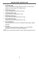
SENDER PANEL LAYOUT Front Panel 1 2 3 Back Panel 7 4 4 5 6
SENDER PANEL DESCRIPTIONS 1 5V DC Power Input Connect the included 5V DC power supply input this port. Once this has been properly connected the power LED will become active. 2 3 RCA Component Input Connect the component source device to this input. 3 2 RCA Analog Stereo Input Connect the source’s analog audio to this input. 4 SPDIF Digital Audio Input Connect the source’s SPDIF digital audio to this input. 5 Optical Digital Audio Input Connect the source’s optical digital audio to this input.
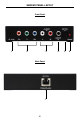
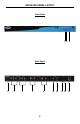
RECEIVER PANEL LAYOUT Front Panel 12 3 Back Panel 4 5 6 7 8 6 9 10 11 12 13
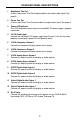
RECEIVER PANEL DESCRIPTIONS 1 Brightness Trim Pot Use this adjustment Trim Pot to brighten/darken the output video signal. See page 9. 2 Focus Trim Pot Use this adjustment Trim Pot to focus/blur the output video signal. See page 9. 3 Power LED Indicator This LED will become active once the included 5V DC power supply is properly connected. 4 5V DC Power Input Connect the included 5V DC power supply input this port. Once this has been properly connected the power LED will become active.
CONNECTING AND OPERATING THE 1:2 COMPONENT AUDIO OVER CAT5 How to Connect the 1:2 Component Audio Over CAT5 1. Connect the component video source to the Component Audio Over CAT5 sending unit using the supplied 3 RCA component cable. 2. Connect audio to the Component audio Over CAT5 sender unit using either user supplied audio cables or the included audio cables. Digital Audio: Use either the digital S/PDIF or optical inputs. Analog Audio: Use the 2 RCA analog stereo inputs.
ADJUSTING THE VIDEO QUALITY The 1:2 Component Audio Over CAT5 receiving unit can adjust both the brightness and focus of the reproduced video signal. Differences in cable skew and distance are factors that can affect these settings. To adjust these settings and tune the video signal please use the steps below. Brightness If the image appears too dim or too bright, adjust the brightness trim pot on the front of the Component/Audio Receiver.
NETWORK CABLE WIRING DIAGRAM Gefen has specifically engineered their products to work with the TIA/EIA-568-B specification. Please adhere to the table below when field terminating cable for use with Gefen products. Failure to do so may produce unexpected results and reduced performance. Pin Color 1 Orange / White 2 Orange 3 Green / White 4 Blue 5 Blue / White 6 Green 7 Brown / White 8 Brown 12345678 CAT-5, CAT-5e, and CAT-6 cabling comes in stranded and solid core types.
SPECIFICATIONS Video Amplifier Bandwidth ....................................................................... 350 MHz Input Video Signal .............................................................................. 1.2 Volts p-p Input Sync Signal ........................................................................ 5 Volts p-p (TTL) Horizontal Frequency Range ................................................................ 15-70 KHz Vertical Frequency Range ...........................................