4x4 Component Matrix Over CAT-5 EXT-COMPAUD-CAT5-444 User Manual www.gefen.
ASKING FOR ASSISTANCE Technical Support: Telephone Fax (818) 772-9100 (800) 545-6900 (818) 772-9120 Technical Support Hours: 8:00 AM to 5:00 PM Monday thru Friday. Write To: Gefen Inc. c/o Customer Service 20600 Nordhoff St Chatsworth, CA 91311 www.gefen.com support@gefen.com Notice Gefen Inc. reserves the right to make changes in the hardware, packaging and any accompanying documentation without prior written notice. 4x4 Component Matrix Over CAT-5 is a trademark of Gefen Inc. © 2008 Gefen Inc.
CONTENTS 1 Introduction 2 Operation Notes 3 Features 4 4x4 Component Matrix Over CAT-5 Front Panel Layout 5 4x4 Component Matrix Over CAT-5 Front Panel Descriptions 6 4x4 Component Matrix Over CAT-5 Back Panel Layout 7 4x4 Component Matrix Over CAT-5 Back Panel Descriptions 8 4x4 Component Audio Over CAT-5 Receiver Panel Layout 9 4x4 Component Audio Over CAT-5 Receiver Panel Description 10 RMT-16IR Remote Description 11 RMT-4IR Remote Description 12 Connecting And Operating The 4x4 Compone
INTRODUCTION Congratulations on your purchase of the 4x4 Component Matrix Over CAT-5. Your complete satisfaction is very important to us. Gefen Gefen delivers innovative, progressive computer and electronics add-on solutions that harness integration, extension, distribution and conversion technologies.
OPERATION NOTES READ THESE NOTES BEFORE INSTALLING OR OPERATING THE 4X4 COMPONENT MATRIX OVER CAT-5 • The extender functionality of the 4x4 Component Matrix Over CAT-5 requires the use of the supplied 1 foot component video and audio jumper cables. These cables must be used to connect the component video and audio output ports to the component video and audio extension input ports. Please see page 12 for details. • For 1080p video, maximum extension is 1000 feet (300 meters).
FEATURES Features • Switches easily between any four component/audio sources • Sends up to four video inputs to any four remote displays • Maintains 1920 x 1200, 1080p, and 2k resolution video • Extends video up to 1000 feet over CAT-5 cable • Discrete IR remote (included) • Serial RS-232 remote port • Rack ears included Package Includes (1) 4x4 Component/Audio CAT5 Matrix (4) Component/Audio over CAT-5 Receiver Units (4) RMT-4 Infrared Remote Controls (4) 1 Foot 5 RCA Component Video/Audio Ca
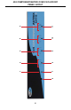
6 7 1 8 2 3 9 4 10 5 11 4X4 COMPONENT MATRIX OVER CAT-5 FRONT PANEL LAYOUT 4
4X4 COMPONENT MATRIX OVER CAT-5 FRONT PANEL DESCRIPTIONS 1 Power LED Indicator This LED will become active once the included 24V DC power adapter is properly connected. 2 Output 1 Source LED Indicator The currently selected source being displayed on Monitor Output 1 will be visually acknowledged by an active LED. There are 4 LED’s, one for each input source. 3 Output 2 Source LED Indicator The currently selected source being displayed on Monitor Output 2 will be visually acknowledged by an active LED.
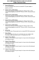
4 5 1 2 6 3 7 4X4 COMPONENT MATRIX OVER CAT-5 BACK PANEL LAYOUT 6
4X4 COMPONENT MATRIX OVER CAT-5 BACK PANEL DESCRIPTIONS 1 Component With Audio Extension Input Connect the included jumper cables between the Component With Audio Outputs (Item 5 on this page) and these inputs. Inputs include component video, analog audio, and digital audio connectors. There are 4 inputs that are used in conjunction with the CAT-5 output ports for extension. 2 IR Blaster Outputs Connect IR emitters/blaster (sold separately, part# EXT-2IREMIT) to these output ports.
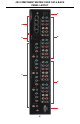
4X4 COMPONENT AUDIO OVER CAT-5 RECEIVER PANEL LAYOUT Front Panel 1 2 3 Back Panel 4 5 6 7 Top Panel 11 8 8 9 10
4X4 COMPONENT AUDIO OVER CAT-5 RECEIVER PANEL DESCRIPTION 1 IR Receiver This receiver will receive commands from both the included RMT-4IR remote control and from other commercial IR remote controls. IR commands from commercial IR remote controls are relayed from this unit back to the 4x4 Component Audio Over CAT-5 sending unit where they will be output by the attached IR Blasters.
RMT-16IR REMOTE DESCRIPTION L LED Indicator The RMT-16IR remote control will allow the user to select which source each of the 4 connected displays will be viewing at the source location. Each of the 4 displays are assigned a group of 4 buttons that correspond to the 4 source inputs. Please use the information below when selecting the desired source for each display.
RMT-4IR REMOTE DESCRIPTION LED Indicator Input Selection Buttons Each extended location with a 4x4 Component Matrix Over CAT-5 Receiver can use an RMT-4IR remote control to choose which source will be viewed by the attached display. Pressing the numbered buttons will switch to the source connected to the same numbered input on the 4x4 Component Matrix Over CAT-5. To use the RMT-4 IR remote, remove the battery cover on the back of the remote to reveal the battery compartment.
CONNECTING AND OPERATING THE 4X4 COMPONENT MATRIX OVER CAT-5 How to Connect the 4x4 Component Matrix Over CAT-5 1. Connect up to 4 component video/audio source devices to the 4x4 Component Matrix Over CAT-5 sending unit using the included 5 RCA component video/audio cables. 2. Optionally, connect up to 4 digital coaxial audio source devices to the 4x4 Component Matrix Over CAT-5 sending unit using one of the RCA cables from the supplied 5 RCA component/audio cable. 3.
OPERATING THE 4X4 COMPONENT MATRIX OVER CAT-5 RECEIVER The 4x4 Component Matrix Over CAT-5 Receiver can be placed at each remote location. Each receiver can switch between the four sources connected to the 4x4 Component Over CAT-5 Matrix sender. The unit has two methods of switching using either the direct selection buttons or the RMT-4IR remote control.
ADJUSTING THE 4X4 COMPONENT MATRIX OVER CAT-5 RECEIVER Each 4x4 Component Matrix Over CAT-5 Receiver has two trim pots used to adjust the brightness and focus of the video output. These adjustment trim pots are located on the front panel of each unit. Please use the guidelines below for adjusting both trim pots. Brightness If the image appears too dim or too bright, adjust the brightness trim pot. 1. Insert a small flathead adjustment tool into the trim pot. 2.
RMT-4IR REMOTE IR CODE CONFIGURATION How to Resolve IR Code Conflicts In the event that IR commands from other remote controls conflict with the supplied RMT-4IR remote control, changing the remote channel will alleviate this issue. The RMT-4IR remote control and the 4x4 Component Matrix Over CAT-5 receiver have DIP SWITCHES for configuring the remote channel that both units use to communicate. These settings must match each other for proper operation.
RS-232 SERIAL CONTROL INTERFACE 12345 12345 6789 6789 Only Pins 2 (RX), 3 (TX), and 5 (Ground) are used on the RS-232 serial interface Binary Table ASCII Corresponding RMT16-IR Button 1 1 2 2 3 3 4 4 5 5 6 6 7 7 8 8 Binary ASCII 0011 0001 0011 0010 0011 0011 0011 0100 0011 0101 0011 0110 0011 0111 0011 1000 9 a b c d e f g Corresponding RMT16-IR Button 9 10 11 12 13 14 15 16 Binary 0011 1001 0110 0001 0110 0010 0110 0011 0110 0100 0110 0101 0110 0110 0110 0111 RS232 Settings Bits per second ..
NETWORK CABLE WIRING DIAGRAM Gefen has specifically engineered their products to work with the TIA/EIA-568-B specification. Please adhere to the table below when field terminating cable for use with Gefen products. Failure to do so may produce unexpected results and reduced performance. Pin Color 1 Orange / White 2 Orange 3 Green / White 4 Blue 5 Blue / White 6 Green 7 Brown / White 8 Brown 12345678 CAT-5, CAT-5e, and CAT-6 cabling comes in stranded and solid core types.
RACK MOUNT INSTALLATION Rack mount ears are provided for installation of this unit into a 1U rack mount space. 1. 2. 3. 4. Locate the side screws on the unit. Remove the front 2 screws that are located closest to the front of the unit. Using the removed screws, screw the rack mounting bracket into the unit. Repeat the procedure on the opposite side of the unit.
SPECIFICATIONS Video Amplifier Bandwidth ....................................................................... 350 MHz Input Video Signal .............................................................................. 1.2 volts p-p Video Resolutions ........................................................................................ 1080p Video Connector ...................................................................... RCA-style RGB x 3 Analog Audio Connector ......................................