
User Guide


7
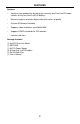
Remote Channel 1:
Default
1 2
Remote Channel 2:
1 2
Remote Channel 3:
1 2
Remote Channel 4:
1 2
Remote Channel 1:
Default
1 2
Remote Channel 2:
1 2
Remote Channel 3:
1 2
Remote Channel 4:
1 2
RMT-16-IR REMOTE CONTROL
4x4 DVI DL Matrix
1
2
3
4
5
6
7
8
OFF
ON
The 4x4 DVI DL Matrix has a bank of 8 confi guration DIP SWITCHES. These
switches are located underneath the unit. Peeling back the black metallic sticker
on the bottom of the 4x4 DVI DL Matrix will reveal the Dip Switch bank. These
service switches are used for a number of confi guration options. By default, all
Dip Switches are in the OFF position. Each setting is outlined below.
IR Remote Channel Confi gurationSwitch 1
IR Remote Channel Confi gurationSwitch 2
Automatic Link Selection \ Dual Link Only Mode Switch 3
Not UsedSwitch 4
Pre-Empahsis For Display Output 1Switch 5
Pre-Empahsis For Display Output 2Switch 6
Pre-Empahsis For Display Output 3Switch 7
Pre-Empahsis For Display Output 4Switch 8
IR REMOTE CHANNEL CONFIGURATION
Dip Switches 1 and 2 relate to the IR remote control channel that is used by the 4x4
DVI DL Matrix and RMT-16-IR remote control. Dip Switch 1 and 2 on the 4x4
DVI DL Matrix must match Dip Switch 1 and 2 on the RMT-16-IR remote control.
Please view the table below to set the channel on 4x4 DVI DL Matrix and IR
remote control. The remote channel for the RMT-16-IR is located underneath it’s
battery cover.
CONFIGURING THE 4X4 DVI DL MATRIX