® 8x1 DVI KVM DL Switcher EXT-DVIKVM-841DL User Manual www.gefen.
ASKING FOR ASSISTANCE Technical Support: Telephone Fax (818) 772-9100 (800) 545-6900 (818) 772-9120 Technical Support Hours: 8:00 AM to 5:00 PM Monday thru Friday PST Write To: Gefen Inc. c/o Customer Service 20600 Nordhoff St Chatsworth, CA 91311 www.gefen.com support@gefen.com Notice Gefen, LLC reserves the right to make changes in the hardware, packaging and any accompanying documentation without prior written notice. 8x1 DVI KVM DL Switcher is a trademark of Gefen, LLC. © 2010 Gefen, LLC.
CONTENTS 1 Introduction 2 Operation Notes 3 Features 4 Panel Layout 5 Panel Descriptions 6 Connecting the 8x1 DVI KVM DL Switcher 7 8x1 DVI KVM DL Remote Description 8 8x1 DVI KVM DL Switcher Remote Installation 9 RMT-8IR Remote and 8x1 DVI KVM Switcher Configuration 10 EDID Modes 12 DL (Dual Link) Only Modes 13 RS-232 Serial Communication 14 RS-232 Serial Control Commands 22 Rack Mount Installation 23 Specifications 24 Warranty
INTRODUCTION Congratulations on your purchase of the 8x1 DVI KVM DL Switcher. Your complete satisfaction is very important to us. Gefen Gefen delivers innovative, progressive computer and electronics add-on solutions that harness integration, extension, distribution and conversion technologies.
OPERATION NOTES READ THESE NOTES BEFORE INSTALLING OR OPERATING THE GEFEN 8X1 DVI KVM DL SWITCHER • The 8x1 DVI KVM DL Switcher will take any of up to eight (8) DVI dual-link or single-link resolution inputs and switch them, one at a time, to a DVI output device such as a display/monitor or projector. Dual link resolutions up to 3840 x 2400 are supported. • The 8x1 DVI KVM DL Switcher is housed in a metal box for better RF shielding.
FEATURES Features • Switches between any eight dual link (or single link) DVI computers • Switches USB 2.
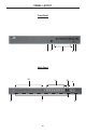
PANEL LAYOUT Front Panel 1 2 4 5 3 Back Panel 10 11 12 9 6 7 4 8
PANEL DESCRIPTIONS 1 External IR Port For connection of external IR extension device such as the Gefen IR Extender (part # EXT-RMT-EXTIR). 2 IR Receiver Receives IR signal from the handheld Infrared remote control unit included with the 8x1 DVI KVM DL Switcher. 3 DVI Signal Status LEDs 1-8 Provide visual confirmation of the currently selected DVI input signal being output to the DVI display device.
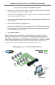
CONNECTING THE 8X1 DVI KVM DL SWITCHER How to Connect the 8x1 DVI KVM DL Switcher 1. Connect your computers’ DVI, USB, and Audio sources to the 8x1 DVI KVM DL Switcher inputs using the supplied cables. 2. Connect your DVI display to the DVI output of the 8x1 DVI KVM DL Switcher using a user-supplied DVI cable. 3. Connect your USB and audio devices to the USB and audio outputs with usersupplied cables. 4. Turn on the DVI display or projector first. 5.
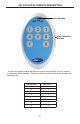
8X1 DVI KVM DL REMOTE DESCRIPTION LED D Indicator Input Selection Buttons The RMT-8IR remote mote control will allow the user to choose which of 8 DVI sources or computers will be selected.
8X1 DVI KVM DL SWITCHER REMOTE INSTALLATION To use the RMT-8IR remote, remove the battery cover on the back of the remote to reveal the battery compartment. Insert the included battery into the open battery slot. The positive (+) side should be facing up. Ensure that both DIP (Dual Inline Package) switches are in the OFF position. Replace the battery cover. The remote ships with 2 batteries. One battery is needed for operation and the other battery is complimentary.
RMT-8IR REMOTE AND 8X1 KVM SWITCHER CONFIGURATION How to Resolve IR Code Conflicts In the event that IR commands from other remote controls conflict with the supplied RMT-8IR remote control, changing the remote channel will alleviate this issue. The RMT-8IR remote control and the 8x1 DVI KVM DL Switcher both have banks of DIP (Dual Inline Package) Switches for configuring the remote channel that both units use to communicate. These settings must exactly match each other for proper operation.
EDID MODES EDID. What is it,, and what is it used for? Under normal circumstances, a computer source device (digital or analog) will require information about a connected device/display to assess what resolutions and features (capabilities) are possible. The source device can then cater its output to create resolutions and/or features that are compatible with the attached device/display. This capability information is called EDID (Extended Display Identification Data).
EDID MODES EDID Modes The diagram below illustrates the 4 DIP switch bank. The 8 DIP switch bank functions are outlined later on this page. DIP SWITCH Function 1 IR Channel 2 IR Channel 3 EDID Mode 4 EDID Lock Mode 1 2 3 4 Use DIP switch 3 to set the desired EDID mode. 1. • LOCAL EDID Mode (Switch 3=OFF) DEFAULT EDID that is stored in the LOCAL memory location is passed to all inputs.
DL (DUAL LINK) ONLY MODES DL ((Dual Link)) Only y Modes The 8 DIP switch bank, located on the underside of the 8x1 DVI KVM DL Switcher cab be used to set each individual input to work in a Dual Link Only mode. These modes should only be enabled if issues occur when using Dual Link sources and displays in the default mode.
RS-232 SERIAL COMMUNICATION What features are available via the RS-232 serial communications port? p The 8x1 DVI KVM DL Switcher can accept commands through the RS-232 serial communications port located on the rear panel. The current RS-232 control features are: • Switching/routing of inputs to outputs without the RMT-8IR remote control. • Switch EDID modes without operating the DIP switches on the underside of the unit. • Managing the EDID bank and EDID that is loaded into the LOCAL EDID.
RS-232 SERIAL CONTROL COMMANDS RS-232 Features RS-232 remote functions are used to control of this product’s features. Features include input to output routing, EDID storage, EDID management, etc. Functions Syntax y The syntax for each function is always the same: #Character as the start flag → Function name → Space ( _ ) as function name end flag → Parameter 1 → Space → Parameter n → Carriage Return ( \r ) → Sample: #FunctionName_param1_param2_param3_param4...\r Syntax is NOT case sensitive.
RS-232 SERIAL CONTROL COMMANDS #EDIDDSTOLO Function The #EDIDDSTOLO function reads the downstream EDID and stores into all local inputs. Syntax y : #EDIDDSTOLO Parameters: None #EDIDDSTOBA Function The #EDIDDSTOBA function reads the downstream EDID and stores it to a specified EDID bank. Syntax y : #EDIDDSTOBA param1 Parameters: param1 EDID bank offset [1 - 7] #EDIDBATOLO Function The #EDIDBATOLO function reads an EDID from an EDID bank and stores it in all inputs.
RS-232 SERIAL CONTROL COMMANDS #DDCTODS Function The #DDCTODS function routes the input DDC to the downstream EDID (passthrough mode). Syntax y : #DDCTODS Parameters: None #DDCTOLO Function The #DDCTOLO function routes the input DDC to the local EDID. Syntax y : #DDCTOLO Parameters: None #DEF Function The #DEF function set the Switcher to the factory default settings.
RS-232 SERIAL CONTROL COMMANDS #LOEDIDTOBA Function The #LOEDIDTOBA function loads the specified EDID file and stores it in a specified EDID bank.
RS-232 SERIAL CONTROL COMMANDS #LOEDIDTOLO Function The #LOEDIDTOLO function loads the specified EDID file to a specified local input. Syntax y : #LOEDIDTOLO param1 param2 Parameters: param1 param2 2 Echo mode [0 - 1] Value Meaning 0 Semi echo mode 1 Full echo mode EDID size [1 - 2] Value Meaning 1 128 byte EDID 2 256 byte EDID #PRBAEDID Function The #PRBAEDID function reads the EDID file from the specified bank and sends it to the serial port.
RS-232 SERIAL CONTROL COMMANDS #PRDSEDID Function The #PRDSEDID function reads the downstream EDID and sends it to the serial port. Syntax y : #PRDSEDID param1 Parameters: param1 File type [0 - 1] Value Meaning 0 .BIN file 1 .TXT file #PRLOEDID Function The #PRLOEDID function reads the local EDID and spools it to the serial port. Syntax y : #PRLOEDID param1 Parameters: param1 File type [0 - 1] Value Meaning 0 .BIN file 1 .
RS-232 SERIAL CONTROL COMMANDS Commands Simplified syntax was used for command implementation for faster operation with the device: # character – isn’t needed, the command name is reduced to 1 letter. The commands are not case-sensitive.
RS-232 SERIAL CONTROL COMMANDS 2. USING SHORT-CUT CHARACTERS TO CHANGE SETTINGS 2.1 HYPERTERMINALtm SETTINGS in Microsoft Windowstm First, please setup correct communications by performing these commands (as shown on the screen shot immediately below): File->Properties->Setting->ASCII Setup Also, please be sure to unmark the check box that says “Send line ends with line feeds.” 2.2 EXAMPLE -- CHANGE THE ROUTED SOURCE Now you are ready to route Display input sources.
RACK MOUNT INSTALLATION Rack mount ears are provided for installation of this unit into a 1U rack mount space. 1. 2. 3. 4. Locate the side screws on the unit. Remove the front 2 screws that are located closest to the front of the unit. Using the removed screws, screw the rack mounting bracket into the unit. Repeat the procedure p on the opposite pp side of the unit.
SPECIFICATIONS Video Amplifier Bandwidth...................................................................165 MHz x 2 Input Video Signal................................................................................1.2 Volts p-p Input DDC Signal...........................................................................5 Volts p-p (TTL) DVI Connector..................................................... DVI-I 29-pin female (digital only) USB Input Connection..................................................
WARRANTY Gefen warrants the equipment it manufactures to be free from defects in material and workmanship. If equipment fails because of such defects and Gefen is notified within two (2) years from the date of shipment, Gefen will, at its option, repair or replace the equipment, provided that the equipment has not been subjected to mechanical, electrical, or other abuse or modifications.
Rev A6 20600 Nordhoff St., Chatsworth CA 91311 1-800-545-6900 818-772-9100 www.gefen.com Pb This product uses UL listed power supplies. fax: 818-772-9120 support@gefen.