
Manual

7
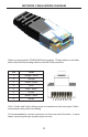
RECEIVER UNIT DESCRIPTIONS
1 Power Indicator
This LED will turn bright blue once the included 5V DC locking power supply
has been properly connected to the unit and the locking power supply has been
connected to an available electrical outlet.
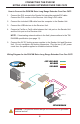
2 Link Indicator
This LED glows bright blue when the Sender Unit and Receiver Unit are
connected using Cat-5 / Cat-6 cable.
3 USB Indicator
This LED glows bright blue when a USB source is connected to the Receiver
Unt.
4 DVI Indicator
ThisLEDasheson(brightblue)andoffwhenaDVIdisplayisconnectedto
the Receiver Unit. The Sender Unit and Receiver Unit must also be connected
using a Cat-5 / Cat-6 cable.
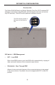
5 Service Port
Mini-USBserviceportusedforupgradingthermware.
6 Link
Connects the Receiver Unit to the Sender Unit using Cat-5 / Cat-6 cable.
7 DVI Out
Connect a DVI display to this DVI-I connector.
8 USB Input Ports (1 - 3)
Connect USB devices to these ports.
9 5 V DC Locking Power Connector
Connect the included 5 V DC locking power supply to this connector.