
Specifications


5
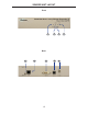
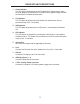
SENDER UNIT DESCRIPTIONS
1 Power Indicator
This LED will turn bright blue once the included 5V DC locking power supply
has been properly connected to the unit and the locking power supply has been
connected to an available electrical outlet.
2 Link Indicator
This LED glows bright blue when the Sender Unit and Receiver Unit are
connected using Cat-5 / Cat-6 cable.
3 USB Indicator
This LED glows bright blue when a USB source is connected to the Sender Unt.
4 DVI Indicator
This LED fl ashes on (bright blue) and off when a DVI video source is connected
to the Sender Unit. The Sender Unit and Receiver Unit must also be connected
using a Cat-5 / Cat-6 cable.
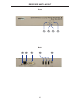
5 Service Port
Mini-USB service port used for upgrading the fi rmware.
6 Link
Connects the Sender Unit to the Receiver Unit using Cat-5 / Cat-6 cable.
7 DVI In
Connect a DVI cable from the computer to this DVI-I connector.
8 USB In
Connects the Sender Unit to the network using an Ethernet cable.
9 5 V DC Locking Power Connector
Connect the included 5 V DC locking power supply to this connector.