3GSDI DVI KVM Audio Over IP Embedder with Local DVI Output EXT-DVIKVM-LAN-L User Manual Release A2
DVI KVM over IP with Local DVI Output Important Safety Instructions GENERAL SAFETY INFORMATION 1. Read these instructions. 2. Keep these instructions. 3. Heed all warnings. 4. Follow all instructions. 5. Do not use this product near water. 6. Clean only with a dry cloth. 7. Do not block any ventilation openings. Install in accordance with the manufacturer’s instructions. 8.
DVI KVM over IP with Local DVI Output Warranty Information Gefen warrants the equipment it manufactures to be free from defects in material and workmanship. If equipment fails because of such defects and Gefen is notified within two (2) years from the date of shipment, Gefen will, at its option, repair or replace the equipment, provided that the equipment has not been subjected to mechanical, electrical, or other abuse or modifications.
DVI KVM over IP with Local DVI Output Contacting Gefen Technical Support Gefen, LLC c/o Customer Service 20600 Nordhoff St. Chatsworth, CA 91311 Telephone: (818) 772-9100 (800) 545-6900 Fax: (818) 772-9120 Email: support@gefen.com Visit us on the Web: www.gefen.com Technical Support Hours: 8:00 AM to 5:00 PM Monday - Friday, Pacific Time DVI KVM over IP with Local DVI Output is a trademark of Gefen, LLC.
DVI KVM over IP with Local DVI Output Operating Notes • Always make sure that the DVI KVM over IP with Local DVI Output is running the latest version of firmware. Go to the Support section of the Gefen Web site to download the latest version of firmware. See Upgrading the Firmware for instruction on performing the upgrade procedure.
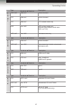
DVI KVM over IP with Local DVI Output IR over IP Serial over IP USB over IP I2S over IP Video over IP Operating Notes Type Sender A D Receiver Description UDP / MC 3344 A X control channel TCP 3344 A X control channel TCP 3240 A X TCP unicast mode only UDP X D 3245 UDP unicast mode only (unicast mode default mode uses UDP, not TCP) UDP / MC X D 3245 multicast mode only Type Sender A D Receiver Description TCP 1234 A X control channel UDP / MC X D 1235 data streaming for both
DVI KVM over IP with Local DVI Output Features and Packing List Features • Extends DVI, USB, RS-232, and stereo analog audio over IP, using a Gigabit Local Area Network.
DVI KVM over IP with Local DVI Output 3GSDI Audio Embedder Table of Contents 01 Getting Started Sender Unit Layout................................................................................................ 2 Front............................................................................................................... 2 Back............................................................................................................... 3 Receiver Unit Layout........................................
DVI KVM over IP with Local DVI Output Table of Contents 03 Appendix Upgrading the Firmware....................................................................................... 46 Developer Notes.................................................................................................. 48 Network Cable Diagram....................................................................................... 49 Rack Tray Installation..............................................................................
DVI KVM Over IP with Local DVI Output 01 Getting Started Sender Unit Layout................................................................................................ 2 Front............................................................................................................... 2 Back............................................................................................................... 3 Receiver Unit Layout.............................................................................
Getting Started Sender Unit Layout Front 1 2 3 4 ID Name Description 1 Power This LED glows steady blue when the unit is connected to an AC outlet and the unit is powered ON. 2 Link This LED glows steady green when the Sender unit and Receiver unit are connected and passing video. 3 Mode Press this button to switch between Graphic Mode and Video Mode. Graphic Mode optimizes still images. Video Mode is best used for optimizing video. See Setting the Video Mode for details.
Getting Started Sender Unit Layout Back 1 2 3 4 5 6 7 ID Name Description 1 DVI In Connect the included DVI cable from this connector to the DVI source. 2 DVI Local Out Used to monitor the DVI source connected to the DVI In port. Connect a DVI cable from this port to a local display. 3 RS-232 Connect the included RS-232 cable from this port to an RS-232 device. See Using RS-232 for details. 4 Line In Connect a 3.
Getting Started Receiver Unit Layout Front 1 2 3 5 6 7 4 ID Name Description 1 Power This LED glows steady blue when the unit is connected to an AC outlet and the unit is powered ON. 2 Link This LED glows steady green when the Sender and Receiver units are connected using Ethernet cable and successfully passing video. 3 Reset Press this button to reset the unit. See Performing a Factory Reset for instructions on restoring the Receiver unit to factory-default settings.
Getting Started Receiver Unit Layout Back 1 2 3 4 ID Name Description 1 DVI Out Connect a DVI cable from this connector to the DVI display. 2 RS-232 Connect the included RS-232 cable from this port to an RS-232 device. See Using RS-232 for details. 3 LAN Connects the Receiver unit to the network (or directly to the Sender unit) using an Ethernet cable. See the next page for installation instructions. 4 5V DC Connect the included 5V DC locking power supply to this power receptacle.
Getting Started Installation Page Title The DVI KVM over IP with Local DVI Output Sender and Receiver units can either be connected over a Local Area Network (LAN) or they can be directly connected to one another. Using a Direct Connection By default, the DVI KVM over IP with Local DVI Output is shipped in Auto IP mode. In Auto IP mode, each Sender and Receiver unit is assigned a unique IP address of 169.254.x.x (where x is a number from 0 to 255).
Getting Started Installation 3. Connect a DVI cable from the DVI display to the DVI Out port on the Receiver unit. NOTE: When using HDMI sources with an HDMI-to-DVI adapter, the HDMI audio will be passed through to the DVI Out connector on the Receiver unit. 4. See Supplementary Connections for instruction on connecting USB, IR, RS-232, and audio cables. 5. Connect the included 2.6 Amp power supply to the Sender unit and the 4 Amp power supply to the Receiver unit.
Getting Started Installation Local Area Network (LAN) Connection IMPORTANT: The use of a Gigabit switch with 8K “jumbo frame” capability is required when connecting the DVI KVM over IP with Local DVI Output to a network. In order to connect the DVI KVM over IP with Local DVI Output to a Local Area Network (LAN), both the Sender and Receiver unit must first be set to DHCP mode or static IP mode.
Getting Started Installation 6. Disconnect the cable between the Sender and Receiver unit. 7. Connect the cable from the Sender unit to the network. Sender unit Connect to LAN Receiver unit Connect to LAN / DHCP server Note that any LAN port on the Receiver unit can be used to connect to the LAN.
Getting Started Installation Supplementary Connections ►► USB (see USB Control for more information on using USB devices) 1. Connect a USB cable from the computer to the USB port on the Sender unit. 2. Connect up to two USB devices to the Receiver unit. ►► Audio (see Audio Connections for more information on using audio devices) 3. Connect a 3.5mm mini-stereo cable from the Line In jack on the Sender unit to an audio source. 4.
Getting Started Installation Sample Wiring Diagram CAT-5 CABLE DVI CABLE USB CABLE AUDIO CABLE RS-232 CABLE Gigabit Switch (Up to 330 ft) Receiver Multimedia PC RS-232 Controlled Device USB Mouse USB Keyboard Sender Powered Speakers or headphones HD Display HD Display EXT-DVIKVM-LAN-L page | 11
DVI KVM Over IP with Local DVI Output 02 Operating the DVI KVM over IP with Local DVI Output Basic Operation.................................................................................................... 14 Displaying the IP Address and Video Channel............................................ 14 Setting the IP Mode...................................................................................... 16 Setting the Video Channel.....................................................................
Operating the DVI KVM over IP with Local DVI Output Basic Operation Displaying the IP Address and Video Channel If the IP address or the video channel of a Sender and/or Receiver unit is not known, then use the following procedure for any Sender or Receiver unit on the network. 1. Press and release the -/Select button on the front panel of the Receiver unit. The current video channel will be displayed in the top-left corner of the screen.
Operating the DVI KVM over IP with Local DVI Output Basic Operation Channel:255 3. Press and hold the -/Select button until the channel number disappears from the screen. The Receiver unit is now changed to the channel 255. 4. After a few moments, the screen will go blank and the IP address of both the Sender and Receiver unit will be displayed in the lower-right corner of the screen. Local IP = Receiver unit Channel:255 Trying to find the gateway... FW: 12-Dec-24 b6e4 Local IP: 169.254.8.
Operating the DVI KVM over IP with Local DVI Output Basic Operation Setting the IP Mode The DVI KVM over IP with Local DVI Output can be set to Auto IP, DHCP, or Static IP mode. By default, the DVI KVM over IP with Local DVI Output is shipped in Auto IP mode. 1. Access the Web interface by entering the IP address of the desired Sender or Receiver unit. Refer to Displaying the IP Address and Video Channel if necessary. 2. Click the Network tab.
Operating the DVI KVM over IP with Local DVI Output Basic Operation Setting the Video Channel In order a Sender and Receiver unit to communicate with one another, they must both be set to the same channel. This is similar to changing the channel on a cable or satellite box in order to view a different program. By default, all Sender and Receiver units are set to channel 0. The channel can be changed using any one of the two methods: 1) Using the -/Select and +/USB buttons on the front panel.
Operating the DVI KVM over IP with Local DVI Output Basic Operation Using the Web Interface 1. Access the Web interface by entering the IP address of the desired Sender or Receiver unit. Refer to (Displaying the IP Address and Video Channel) if necessary. 2. Click the Network tab. The current channel is displayed within the Network Mode window group. 3. Click the Channel Selection drop-down list and select the desired channel. Channel numbers can range from 0 to 255. 4.
Operating the DVI KVM over IP with Local DVI Output Basic Operation Enabling or Disabling Video over IP This feature is useful for masking video. Disabling the video on the Sender unit will mask the video on all connected Receiver units (multicast mode only). To mask the video on selected Receiver units, disable the video on the desired Receiver units. 1. Access the Web interface by entering the IP address of the desired Sender or Receiver unit.
Operating the DVI KVM over IP with Local DVI Output Unicast and Multicast Modes Configuring Unicast Mode The term unicast is used to describe a configuration where information is sent from one point to another point. It is possible to have multiple Sender and Receiver units connected in a system. However, in unicast mode a Sender unit can communicate with only one Receiver unit at a time. In unicast mode, the DVI KVM over IP with Local DVI Output functions similiar to a DVI KVM switcher.
Operating the DVI KVM over IP with Local DVI Output Unicast and Multicast Modes 3. Click the Unicast button under the Network Mode group. When selected, the Unicast button will be highlighted in blue. 4. Click the Save button in the lower-right corner of the Network Mode group. 5. The following message will be displayed, at the top of the page, indicating that the casting mode has been applied to the Sender or Receiver unit. 6.
Operating the DVI KVM over IP with Local DVI Output Unicast and Multicast Modes Switching between Sender units in Unicast mode When multiple Sender and Receiver units are used in unicast mode, the DVI KVM over IP with Local DVI Output behaves as a switcher. In unicast mode, a Sender unit can communicate with only one Receiver unit at a time. In the example below, we will switch Receiver unit R1 to receive the DVI source on Sender unit S1. Figure 2.
Operating the DVI KVM over IP with Local DVI Output Unicast and Multicast Modes Figure 2.3 - Unicast mode: Receiver unit R1 is now connected to Sender unit S1. Receiver unit DVI Out 2 2 R Sender unit Receiver unit 5 S 2 1 R 3 DVI Out LAN Sender unit DVI In S 2 1 Sender unit DVI In S 1 5 DVI In Note that each of the Sender units in Figure 2.3 is assigned a unique channel number.
Operating the DVI KVM over IP with Local DVI Output Unicast and Multicast Modes In order to solve the problem, in Figure 2.4, we would need to make sure that each of the Sender units is set to a unique channel number. When using unicast mode, each of the Sender units must be assigned a unique channel and should never be changed. Use the Receiver unit to switch (channels) between Sender units.
Operating the DVI KVM over IP with Local DVI Output Unicast and Multicast Modes Configuring Multicast Mode The term multicast is used to describe a configuration where information is sent from one or more points to a set of other points. For example, a single Sender unit can transmit data to multiple Receiver units. In addition, if multiple Sender units are used, each Sender unit can transmit data to any Receiver that is not already receiving data from another Sender unit.
Operating the DVI KVM over IP with Local DVI Output Unicast and Multicast Modes 3. Click the Multicast button under the Network Mode group. When selected, the Multicast button will be highlighted in blue. 4. Click the Save button in the lower-right corner of the Network Mode group. The following message will be displayed, at the top of the page, indicating that the casting mode has been applied to the Receiver unit.
Operating the DVI KVM over IP with Local DVI Output Using RS-232 The DVI KVM over IP with Local DVI Output supports RS-232 pass-through, allowing the control of remote RS-232 devices. The Sender and Receiver unit which are being used to pass-through the RS-232 data must be set to the same baud rate as the RS-232 host and client. In the example below, the Gefen 4x1 HD Switcher w/ Audio Decoding (Gefen part no. GTV-AUDDEC-N) has been connected to Receiver unit A. This is the RS-232 client.
Operating the DVI KVM over IP with Local DVI Output Using RS-232 1. Access the Web interface for the Sender unit. 2. Click the Functions tab. 3. Locate the Serial over IP group and change the RS-232 settings to match the settings of the RS-232 device that is being used. In this case, we need to use the settings from Table 2.1 4. Make sure that the Enable Serial over IP box is checked. NOTE: If Enable Serial over IP is not checked, then RS-232 pass-through will be disabled. 5.
Operating the DVI KVM over IP with Local DVI Output Using RS-232 RS-232 under Unicast Mode In unicast mode, a Sender unit will be able to communicate with only one Receiver unit at a time. Figure 2.7 - In unicast mode, the host can talk to only one RS-232 device at a time.
Operating the DVI KVM over IP with Local DVI Output USB Control USB under Unicast Mode When connecting USB devices to the DVI KVM over IP with Local DVI Output, the functionality is similar to that of video and RS-232. NOTE: By default, the DVI KVM over IP with Local DVI Output Sender and Receiver units are shipped in unicast mode. As an example, we will start with our original diagram and connect a computer to Sender unit S2 and a keyboard and mouse device to Receiver unit R2.
Operating the DVI KVM over IP with Local DVI Output USB Control 4. Locate the USB over IP group and make sure the Enable USB over IP box is checked. This is the default setting. 5. In unicast mode, the Operation Mode is automatically set to Active on link and cannot be changed. 6. Make sure that the USB Mouse Mode is set to High Resolution. This is the default setting.
Operating the DVI KVM over IP with Local DVI Output USB Control USB under Multicast Mode When connecting USB devices to the DVI KVM over IP with Local DVI Output, the functionality is similar to that of video and RS-232. There are two USB modes available in multicast mode: Active per request mode and Active on link mode. For an example, we’ll begin with the last diagram and connect another keyboard and mouse device to Receiver R1. This will allow us to control the computer from two separate locations.
Operating the DVI KVM over IP with Local DVI Output USB Control In multicast mode, the Operation Mode for both Sender and Receiver units are automatically set to Active per request mode. Under Active per request mode, multiple USB devices may be present on one or more Receiver units. However, only one Receiver unit can have USB control at a time. By default, the first Receiver unit connected to the system will have USB control.
Operating the DVI KVM over IP with Local DVI Output USB Control Assigning USB control under Active per request mode Now, let’s look at an example of switching USB control between two Receiver units. Using the diagram on the previous page, we want Receiver unit R1 to have USB control. To assign USB control to another Receiver unit, use the following steps: 1. Press and hold the -/Select button on the desired Receiver unit, for at least two seconds.
Operating the DVI KVM over IP with Local DVI Output USB Control Active on link mode Under Active on link mode, a maximum of four USB devices can be used within a system. In the diagram, on the previous page, the system is already using the maximum number of USB devices (2 USB devices per Receiver). If we had two more Receiver units (making a total of four Receiver units), we could have connected a single USB device to each Receiver unit. To switch to Active on link mode, follow the instruction below. 1.
Operating the DVI KVM over IP with Local DVI Output EDID Management The DVI KVM over IP with Local DVI Output features EDID Management. Before the source can send video (and/or audio) data, the source device (connected to each Sender unit) reads the EDID (Extended Display Identification Data) from the displays which are connected to each Receiver unit. The EDID contains information about what type of audio/ video data can be sent by each source.
Operating the DVI KVM over IP with Local DVI Output EDID Management Using the Downstream EDID By default, the (downstream) EDID from the display, connected to the Receiver unit, is used. If the internal EDID is being used (see Using the Internal DVI EDID), then use the following procedure to revert to the downstream EDID. 1. Access the Web interface for the Receiver unit. 2. Click the Functions tab. 3. Make sure that the Copy EDID of Connected Display box is checked. This is the default setting.
Operating the DVI KVM over IP with Local DVI Output Audio Connections Audio works in both unicast and multicast modes. To illustrate how audio works with the DVI KVM over IP with Local DVI Output, we will set up an audio source (computer) and some powered speakers. Connect a 3.5mm-to-3.5mm mini-stereo cable from the Line Out jack on the computer’s audio card to the Line In jack on the Sender unit. Connect to Line Out on computer Sender unit Note that any audio device (e.g. MP3 player, etc.
Operating the DVI KVM over IP with Local DVI Output Audio Connections In the diagram below, the mouse and keyboard USB devices have been removed from Sender unit S2 and Receiver unit R2, for purposes of clarity. Arrowheads indicate the audio signal path. Figure 2.12 - Speaker connections in unicast mode.
Operating the DVI KVM over IP with Local DVI Output Audio Connections Using HDMI Sources Hi-Def (HDMI) sources can be connected to the DVI KVM over IP with Local DVI Output when using HDMI-to-DVI adapters on the Sender and Receiver units. HDMI audio is passed through to the DVI Out port on the Receiver unit. The DVI KVM over IP with Local DVI Output will not pass content from HDCP sources such as Blu-ray players and Playstation® console systems. If a 3.
Operating the DVI KVM over IP with Local DVI Output Setting the Video Mode The DVI KVM over IP with Local DVI Output provides two video modes: Video Mode and Graphic Mode. Consecutively pressing the Mode button on the Sender unit will toggle between Video Mode and Graphic Mode. ►► Video Mode If the DVI signal is motion video, then press the Mode button on the front panel of the Sender unit until Video Mode is displayed. This mode will optimize the frame rate.
Operating the DVI KVM over IP with Local DVI Output Performing a Factory Reset To reset a DVI KVM over IP with Local DVI Output Sender and / or Receiver unit to factorydefault settings, follow the instructions below. Sender Unit 1. Disconnect the power from the Sender unit. 2. Press and hold the Mode button. 3. While continuing to press the Mode button, reconnect the power. 4. Continue holding the Mode button until both Power and Link indicators begin to flash. 5.
DVI KVM Over IP with Local DVI Output 03 Appendix Upgrading the Firmware....................................................................................... 46 Developer Notes.................................................................................................. 48 Network Cable Diagram....................................................................................... 49 Rack Tray Installation...........................................................................................
Appendix Upgrading the Firmware The following items are required to upgrade the firmware: • Gefen DVI KVM over IP with Local DVI Output • Computer (Mac or PC) • Firmware files 1. Download the firmware for the DVI KVM over IP with Local DVI Output from the Gefen Web site. 2. Extract both firmware files from the .ZIP file. The .ZIP file contains two files: ►► TX_host_kernel_A511_webfwh_v[version]d.bin (Sender unit) ►► RX_client_kernel_A511_webfwc_v[version]d.bin (Receiver unit) 3.
Appendix Upgrading the Firmware 8. Once the firmware upgrade process has completed, the DVI KVM over IP with Local DVI Output will reboot. 9. Repeat the process for each Sender and Receiver unit in the system.
Appendix Developer Notes The following information is intended for developers that use the DVI KVM over IP with Local DVI Output product as part of their application. To change the routing on the Sender and Receiver unit, the following URL needs to be issued: http://IP/cgi-bin/query.cgi?callback=jQuery15101605335909232362_1 370475364360&cache=false&nocache=1370480983843&cmd=astparam+s+mul ticast_ip+225.0.100.
Appendix Network Cable Diagram Front of RJ-45 Connector 1 2 3 4 5 6 7 8 Gefen recommends the TIA/EIA-568-B wiring option. Use the table below when field-terminating cable for use with Gefen products.
Appendix Rack Tray Installation The following illustrations provide instructions for installing the Sender and/or Receiver unit(s) in the Gefen 1U Rack Tray (Gefen part no. EXT-RACK-1U). Step 1 Turn unit upside down. Step 2 Remove rubber feet. Step 3 Line up holes on unit and rack tray. Step 4 Install countersink screws . Step 5 Ensure the unit is installed securely. Step 6 Unit has been installed into rack tray.
Appendix Specifications Supported Formats Resolutions (max.
Stretch it. Switch it. Split it. Gefen’s got it. ® 20600 Nordhoff St., Chatsworth CA 91311 1-800-545-6900 818-772-9100 fax: 818-772-9120 www.gefen.com support@gefen.com Pb This product uses UL or CE listed power supplies.