® DVI RS232 Extender EXT-DVIRS232-CAT5N User Manual www.gefen.
ASKING FOR ASSISTANCE Technical Support: Telephone Fax (818) 772-9100 (800) 545-6900 (818) 772-9120 Technical Support Hours: 8:00 AM to 5:00 PM Monday thru Friday PST. Write To: Gefen LLC c/o Customer Service 20600 Nordhoff St Chatsworth, CA 91311 www.gefen.com support@gefen.com Notice Gefen LLC reserves the right to make changes in the hardware, packaging and any accompanying documentation without prior written notice.
CONTENTS 1 Introduction 2 Features 3 Operation Notes 4 Sender Panel Layout 5 Sender Panel Descriptions 6 Receiver Panel Layout 7 Receiver Panel Descriptions 8 Connecting The DVI RS232 Extender 9 How to Equalize The Video Signal 10 Additional DIP Switch Functions 11 Network Cable Wiring Diagram 12 RS-232 Serial Control Interface 13 Specifications 14 Warranty
INTRODUCTION Congratulations on your purchase of the DVI RS232 Extender. Your complete satisfaction is very important to us. Gefen Gefen is a unique product line catering to the growing needs for innovative home theater solutions. We specialize in total integration for your home theater, while also focusing on going above and beyond customer expectations to ensure you get the most from your hardware. We invite you to explore our distinct product line and hope you find your solutions.
FEATURES Features • Supports resolutions up to 1080p, 2K, and 1920 x 1200 • Sends video at distances of up to 300 feet (1080i) / 150 feet (1080p) • Small and compact • Improved compensation for cable skew • Audio and video are transmitted digitally over the CAT-5, CAT-5e or CAT-6 cable for zero signal loss • Eliminates equipment noise in the viewing environment Package Includes (1) DVI RS232 Extender Sender Unit (1) DVI RS232 Extender Receiver Unit (1) 6 Foot DVI Cable (M-M) (1) 6 Foot RS-232 Ca
OPERATION NOTES READ THESE NOTES BEFORE INSTALLING OR OPERATING THE DVI RS232 EXTENDER • Use two industry standard CAT-5, CAT-5e or CAT-6 cables to operate the DVI RS232 Extender. Gefen recommends CAT-6 cabling for maximum performance. • For 1080i video, maximum extension is 300 feet (91 meters). • This product features the option to force the output color space to RGB and/ or use a pre-programmed EDID.
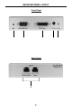
SENDER PANEL LAYOUT Front Panel 1 2 3 4 Back Panel 5 4
SENDER PANEL DESCRIPTIONS 1 5V DC Power Supply Input Connect the 5V DC external power supply to this port. 2 Power LED Indicator This LED will become active once the included 5V DC power supply is properly connected between the unit and an open wall power socket. 3 DVI Input Connect the DVI source into this port. 4 RS-232 Input This port is used to extend the RS-232 signals. Please see page 5 for complete details on the serial communication features that are used on this product.
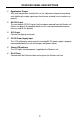
RECEIVER PANEL LAYOUT Front Panel 1 2 3 Back Panel 6 6 4 5
RECEIVER PANEL DESCRIPTIONS 1 Equalization Trimpot With auto-equalization switched off, use this adjustment trimpot for equalizing and stabilizing the video signal over the distance selected (see instructions on page 9). 2 RS-232 Output This port outputs RS-232 signals that have been received from the Sender unit. Please see page 5 for complete details on the serial communication features that are used on this product. 3 DVI Output Connect the display to this port.
CONNECTING THE DVI RS232 EXTENDER 1. Connect the DVI source to the DVI RS232 Extender sending unit’s DVI input port using the supplied DVI cable. 2. Connect the RS-232 source to the DVI RS232 Extender sending unit’s RS-232 input port using the supplied DB-9 serial cable. 3. Connect the DVI RS232 Extender sending and receiving units together using two user supplied CAT-5, CAT-5e or CAT-6 cables. NOTE: If field terminating network cable, please adhere to the TIA/EIA568B specification.
HOW TO EQUALIZE THE VIDEO SIGNAL The DVI RS232 Extender has built-in auto equalization that will automatically tune out any unwanted video noise. This feature is reliable with premium cable runs up to a maximum of 130 feet. If your cable run is beyond 130 feet, it may be necessary to use manual equalization. The sender and receiver units both have sets of DIP switches located on the underside of their enclosure. Remove the silver metallic tape to expose these DIP switches.
ADDITIONAL DIP SWITCH FUNCTIONS FORCE RGB AND PRE-PROGRAMMED EDID FEATURES DIP switch 1 on the 4-bank DIP switch located on the underside of receiver unit enables and disables the automatic equalization function. Additional features can be enabled by using the other DIP switches on this bank. FORCING THE RGB COLOR SPACE In some cases, the output video may have a pink or green tint. This usually is attributed to the output device (e.g. display) not supporting the color space being used by the source device.
NETWORK CABLE WIRING DIAGRAM Gefen has specifically engineered their products to work with the TIA/EIA-568-B specification. Please adhere to the table below when field terminating cable for use with Gefen products. Failure to do so may produce unexpected results and reduced performance. Pin Color 1 Orange / White 2 Orange 3 Green / White 4 Blue 5 Blue / White 6 Green 7 Brown / White 8 Brown 12345678 CAT-5, CAT-5e, and CAT-6 cabling comes in stranded and solid core types.
RS-232 SERIAL CONTROL INTERFACE What features are available via the RS-232 serial communications port? The DVI RS-232 Extender can accept commands through the RS-232 serial communications port located on the rear panel. What pins are used for communication with the DVI RS-232 Extender? Only pins 2 (Receive), 3 (Transmit), and 5 (Ground) are used for communication. A null-modem adapter should not be used with this product.
SPECIFICATIONS Video Amplifier Bandwidth ....................................................................... 165 MHz Input Video Signal .............................................................................. 1.2 Volts p-p Input DDC Signal ......................................................................... 5 Volts p-p (TTL) Single Link Range ................................................................... 1080p/1920 x 1200 DVI Connector ...............................................
WARRANTY Gefen warrants the equipment it manufactures to be free from defects in material and workmanship. If equipment fails because of such defects and Gefen is notified within two (2) years from the date of shipment, Gefen will, at its option, repair or replace the equipment, provided that the equipment has not been subjected to mechanical, electrical, or other abuse or modifications.