
User manual


5
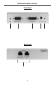
SENDER PANEL DESCRIPTIONS
1 5V DC Power Supply Input
Connect the 5V DC external power supply to this port.
2 Power LED Indicator
This LED will become active once the included 5V DC power supply is properly
connected between the unit and an open wall power socket.
3 DVI Input
Connect the DVI source into this port.
4 RS-232 Input
This port is used to extend the RS-232 signals. Please see page 5 for complete
details on the serial communication features that are used on this product.
5 RJ-45 Ports
Use these ports to connect the Ethernet cables connecting the Sender and
Receiver together and the other Ethernet channel used for the RS-232 back-
channel.