:5 Splitter For Over CAT-5 EXT-HDMI-CAT5-145 User Manual www.gefen.
ASKING FOR ASSISTANCE Technical Support: Telephone Fax (818) 772-9100 (800) 545-6900 (818) 772-9120 Technical Support Hours: 8:00 AM to 5:00 PM Monday thru Friday. Write To: Gefen Inc. c/o Customer Service 20600 Nordhoff St Chatsworth, CA 91311 www.gefen.com support@gefen.com Notice Gefen Inc. reserves the right to make changes in the hardware, packaging and any accompanying documentation without prior written notice. 1:5 Splitter For HDMI Over CAT-5 is a trademark of Gefen Inc. © 2008 Gefen Inc.
CONTENTS 1 Introduction 2 Operation Notes 3 Features 4 Sender Panel Layout 5 Sender Panel Descriptions 6 Receiver Panel Layout 7 Receiver Panel Descriptions 8 Connecting And Operating The 1:5 Splitter For HDMI Over CAT-5 9 EDID Modes 10 Equalization & Boost Settings 11 Network Cable Wiring Diagram 12 Specifications 13 Warranty
INTRODUCTION Congratulations on your purchase of the 1:5 Splitter For HDMI Over CAT-5. Your complete satisfaction is very important to us. Gefen Gefen delivers innovative, progressive computer and electronics add-on solutions that harness integration, extension, distribution and conversion technologies.
OPERATION NOTES READ THESE NOTES BEFORE INSTALLING OR OPERATING THE 1:5 SPLITTER FOR HDMI OVER CAT-5 • 1:5 Splitter For HDMI Over CAT-5 will split the HDMI signal to 5 HDMI outputs. 4 of these outputs can be sent over CAT-5, CAT-5e or CAT-6 cables to remote locations while the last output can be used for local use.
FEATURES Features • HDMI Video Distribution to up to 5 local displays or 4 remote • 300 ft.
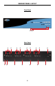
SENDER PANEL LAYOUT Front Panel 1 2 3 Back Panel 4 7 8 5 4 9 5 4 9 5 9 4 4 5 9 6 9
SENDER PANEL DESCRIPTIONS 1 Reset Button Pressing this button will reset the unit and cause the source to re-detect the EDID. This is useful for when the EDID mode on the rear panel is changed. 2 Active LED Indicator This LED will become active when a valid link between the 1:5 Splitter For HDMI Over CAT-5 sender and the source has been established. 3 Power LED indicator This LED will become active once the included 24V DC power supply has been properly connected to the sender unit.
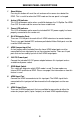
RECEIVER PANEL LAYOUT Front Panel 1 2 3 4 Back Panel 5 6 6
RECEIVER PANEL DESCRIPTIONS 1 Equalization Trim Pot This Trim Pot is used to equalize the incoming HDMI signal to account for variances in CAT cable skew. By default, the Auto EQ feature is enabled and this Trim Pot does not need to be adjusted. In the event that manual EQ mode is enabled, this Trim Pot will be used to equalize the signal. 2 HDMI Output Port Connect an HDMI capable display to this output port.
CONNECTING AND OPERATING THE 1:5 SPLITTER FOR HDMI OVER CAT-5 How to Connect the 1:5 Splitter For HDMI Over CAT-5 1. Connect the HDMI source device to the 1:5 Splitter For HDMI Over CAT-5 sender unit using the supplied HDMI cable. 2. Connect up to 4 of the HDMI outputs to the HDMI jumper inputs using the supplied short HDMI jumper cables. The fifth port can be used for local HDMI output to a display.
EDID MODES EDID (Extended Display Identification Data) contains information on the resolution and general capabilities of a display device. This information is used by the source device to output a compatible signal that the display can accept. This information can even be used by some source devices to limit the output of resolutions and features that the display is not capable of accepting. In single source and single device setup, EDID can effectively ensure compatibility with display and source.
EQUALIZATION & BOOST SETTINGS Each 1:5 Splitter For HDMI Over CAT-5 receiver contains a Dip Switch bank located on the underside of the unit. This bank of 4 Dip Switches are covered with a piece of silver metallic tape. These Dip Switches will modify boost settings and change the equalization mode. EQUALIZATION MODES Dip Switch 1 is used to select the equalization mode. There are 2 EQ modes to select from.
NETWORK CABLE WIRING DIAGRAM Gefen has specifically engineered their products to work with the TIA/EIA-568-B specification. Please adhere to the table below when field terminating cable for use with Gefen products. Failure to do so may produce unexpected results and reduced performance. Pin Color 1 Orange / White 2 Orange 3 Green / White 4 Blue 5 Blue / White 6 Green 7 Brown / White 8 Brown 12345678 CAT-5, CAT-5e, and CAT-6 cabling comes in stranded and solid core types.
SPECIFICATIONS Video Amplifier Bandwidth ....................................................................... 165 MHz Input Video Signal .............................................................................. 1.2 Volts p-p Input DDC Signal ......................................................................... 5 Volts p-p (TTL) Single Link Range ................................................................... 1080p/1920 x 1200 HDMI Video Connector .............................................
Rev X1 20600 Nordhoff St., Chatsworth CA 91311 1-800-545-6900 818-772-9100 www.gefen.com fax: 818-772-9120 support@gefen.