CAT5 4X Extender EXT-HDMI-CAT5-4X User Manual www.gefen.
ASKING FOR ASSISTANCE Technical Support: Telephone Fax (818) 772-9100 (800) 545-6900 (818) 772-9120 Technical Support Hours: 8:00 AM to 5:00 PM Monday thru Friday. Write To: Gefen Inc. c/o Customer Service 20600 Nordhoff St Chatsworth, CA 91311 www.gefen.com support@gefen.com Notice Gefen Inc. reserves the right to make changes in the hardware, packaging and any accompanying documentation without prior written notice. HDMI CAT5 4X Extender is a trademark of Gefen Inc. © 2008 Gefen Inc.
CONTENTS 1 Introduction 2 Operation Notes 3 Features 4 Sender Panel Descriptions 5 Receiver Panel Descriptions 6 Connecting And Operating The Hdmi Cat5 4x Extender 7 Manual Equalization Procedure 8 Dip Switch Location Diagram 9 Network Cable Wiring Diagram 10 Rack Mount Installation 11 Mounting Plate Installation 12 Specifications 13 Warranty
INTRODUCTION Congratulations on your purchase of the HDMI CAT5 4X Extender. Your complete satisfaction is very important to us. Gefen Gefen delivers innovative, progressive computer and electronics add-on solutions that harness integration, extension, distribution and conversion technologies.
OPERATION NOTES READ THESE NOTES BEFORE INSTALLING OR OPERATING THE HDMI CAT5 4X EXTENDER • The HDMI CAT5 4X Extender and HDMI CAT5 MSR units are housed in a metal box for better RF shielding. • The maximum cable extension is 300 feet (91 meters) for video resolutions of 1080i and below. • The maximum cable extension is 150 feet (45 meters) for video resolutions of 1080p. • The DDC cable (for each pair or extensions) does not need to be run if the source does not require HDCP or DDC.
FEATURES Features • Easily distribute four HDMI sources to four remote HDMI displays • Extends video signals up to 300 feet over CAT-5, CAT-5e or CAT-6 network cable • Maintains 1920 x 1200, 1080p, and 2k resolution video Package Includes (1) 4x HDMI CAT5 Sender (4) HDMI CAT5 MS Receivers (4) 6 Foot HDMI Cable (M-M) (4) 5V Dc Power Supply (1) 24V Dc Power Supply (1) Set Of Rack Ears 3
4 24V DC Power Input Video 1 RJ45 Outputs Video 1 HDMI Input Video 2 RJ45 Outputs Video 2 HDMI Input Back Panel Video 3 RJ45 Outputs Front Panel Video 3 HDMI Input Video 4 RJ45 Outputs Video 4 HDMI Input Power LED SENDER PANEL DESCRIPTIONS
RECEIVER PANEL DESCRIPTIONS Front Panel HDMI Output EQ trim pot 5V DC Power input Power LED Indicator Back Panel DDC RJ-45 Port 5 VIDEO RJ-45 Port
CONNECTING AND OPERATING THE HDMI CAT5 4X EXTENDER How to Connect the HDMI CAT5 4X Extender 1. Connect your sources (up to four) to the HDMI CAT5 4X Extender unit’s HDMI inputs using the supplied HDMI cables. 2. Connect your displays (up to four) to the HDMI CAT5 MSR receiver unit’s HDMI outputs using user supplied HDMI cables. 3. Connect both CAT-5, CAT-5e or CAT-6 cables (DDC and Video) between the HDMI CAT5 4X Extender and each HDMI CAT5 MSR receiver.
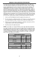
MANUAL EQUALIZATION PROCEDURE The HDMI CAT5 4X Extender and HDMI CAT5 MSR receiver units both have sets of dip switches located on the underside of their casings. There is a piece of silver metallic tape that must be removed to expose these dip switches. The HDMI CAT5 4X Extender unit carries 4 banks of 4 dip switches. Each HDMI CAT5 MSR receiver carries one bank of 4 dip switches. Dip switches 1 and 2 on both the sending and receiving units are used in this procedure. Dip switches 3 and 4 are not used.
DIP SWITCH LOCATION DIAGRAM HDMI CAT5 4X Extender FRONT 1 2 3 Remove Tape 4 Boost Dip Switches HDMI CAT5 MSR Equalization Trim Pot Remove Tape 1 2 3 4 Auto EQ Dip Switches 8
NETWORK CABLE WIRING DIAGRAM Gefen has specifically engineered their products to work with the TIA/EIA-568-B specification. Please adhere to the table below when field terminating cable for use with Gefen products. Failure to do so may produce unexpected results and reduced performance. Pin Color 1 Orange / White 2 Orange 3 Green / White 4 Blue 5 Blue / White 6 Green 7 Brown / White 8 Brown 12345678 CAT-5, CAT-5e, and CAT-6 cabling comes in stranded and solid core types.
RACK MOUNT INSTALLATION Rack mount ears are provided for installation of this unit into a 1U rack mount space. 1. 2. 3. 4. Locate the side screws on the unit. Remove the front 2 screws that are located closest to the front of the unit. Using the removed screws, screw the rack mounting bracket into the unit. Repeat the procedure on the opposite side of the unit.
MOUNTING PLATE INSTALLATION Mounting Plate Installation 1 Remove the rubber feet covering the screws off the bottom of the unit. Remove the screws. 2 3 Line up the mounting plates and screw it on to the unit.
SPECIFICATIONS Video Amplifier Bandwidth ..............................................................4 x 165 MHz Input Video Signal .......................................................................... 1.2 Volts p-p Input DDC Signal ..................................................................... 5 Volts p-p (TTL) Single Link Range ..............................................................1080p / 1920 x 1200 HDMI Connector Type .....................................................