Wireless USB 2.0 Extender USER MANUAL www.gefen.
ASKING FOR ASSISTANCE Technical Support: Telephone Fax (818) 772-9100 (800) 545-6900 (818) 772-9120 Technical Support Hours: 8:00am to 5:00pm Monday thru Friday Write To: Gefen, Inc. c/o Customer Service 20600 Nordhoff St. Chatsworth, CA 91331 support@gefen.com www.gefen.com Notice Gefen Inc. reserves the right to make changes in the hardware, packaging and any accompanying documentation without prior written notice. Wireless USB 2.0 Extender is a trademark of Gefen Inc. © 2007 Gefen Inc.
TABLE OF CONTENTS 1 Introduction 2 How It Works 3 Panel Layout 4 Before You Begin / Connecting Wireless USB Hub / Establishing Wireless Communication 5 Checking the Installation 6 Viewing and Changing the 802.11g Radio Channel 7 Changing the 802.11g Radio Channel 8 Changing the 802.11g Radio Channel 9 Pairing a Wireless USB 2.0 Sender and Receiver 10 Pairing a Wireless USB 2.
INTRODUCTION This manual explains the installation and operation of the Wireless USB 2.0 Extender. The instructions in this guide assume a general knowledge of computer installation procedures, wireless network installation requirements, and some understanding of USB devices. NOTE: Notes give additional information that could make installation easier. To complete the installation, you will also require the following items that are not included with the product: • USB 1.1 or 2.
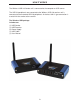
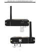
HOW IT WORKS The Wireless USB 2.0 Sender unit is connected to the computer or USB source. The USB 2.0 peripherals are connected to the Wireless USB 2.0 receiver unit is connected to the extended USB 2.0 peripherals. A wireless 802.11 type connection is used to link the sender to the receiver.
WIRELESS USB 2.
WIRELESS USB 2.
BEFORE YOU BEGIN 1. Set up the host computer in an appropriate location. 2. Determine where you want to locate the USB device(s). 3. Determine suitable locations for the Wireless USB 2.0 Sender unit and the Wireless USB 2.0 Receiver unit such that they will be able to maintain wireless communication. Physical obstacles and other radio wave emitting devices can cause interference that will reduce the maximum distance and data rate between the Wireless USB 2.0 Sender unit and the Wireless USB 2.
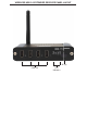
CHECKING THE INSTALLATION Once the Activity LED’s on the Wireless USB 2.0 Sender unit and Wireless USB 2.0 1. Check that the Power LED’s on the Wireless USB 2.0 Sender unit and Wireless USB 2.0 Receiver unit are both on. 2. Check that the Link LED’s on the Wireless USB 2.0 Sender unit and Wireless USB 2.0 Receiver unit are both on. 3. Check that the Host LED’s on the Wireless USB 2.0 Sender unit and Wireless USB 2.0 Receiver unit are both on. 4.
VIEWING AND CHANGING THE 802.11g RADIO CHANNEL The following instructions are for advanced users only. These instructions should only be executed if specifically required and if you are comfortable with the operations. Under normal operating conditions, you should not need to view or change the 802.11g Radio Channel. Viewing the Current 802.11g Radio Channel NOTE: Radio Channel viewing can be done on either the Wireless USB 2.0 Sender unit or the Wireless USB 2.0 Receiver unit. The procedure is the same.
VIEWING CHANGING THE 802.11g RADIO CHANNEL (CONT...) The Wireless USB 2.0 Extender can operate on one of three 802.11g radio channels. Each radio channel broadcasts data in a different frequency band within the 2.4GHz range. The Wireless USB 2.0 Extender can be configured to operate on channels: 1, 6, and 11. By selecting a different Radio Channel, you can try to find a channel with minimal radio interference. This can improve signal quality and data rates.
VIEWING CHANGING THE 802.11g RADIO CHANNEL (CONT...) 5. Once the desired 802.11g Radio Channel is displayed, press and hold the Pair/CH button for 10 seconds. The button can be released when the Host, Link and Activity LED’s start to blink rapidly. NOTE: If the LED’s do not start blinking rapidly within 20 seconds release the button and confirm that the LED pattern still shows your desired channel pattern. If it does, repeat step 5. If it does not, return to step 4. 6.
PAIRING A WIRELESS USB 2.0 SENDER AND RECEIVER The following instructions are for advanced users only. These instructions should only be executed if specifically required and if you are comfortable with the operations. Under normal operating conditions, you should never need to pair a Wireless USB 2.0 Sender unit and a Wireless USB 2.0 Receiver unit. Paired units are defined as a Wireless USB 2.0 Sender unit and a Wireless USB 2.
PAIRING A WIRELESS USB 2.0 SENDER AND RECEIVER (CONT...) 4. Wait for the LED’s on the Wireless USB 2.0 Sender unit and the Wireless USB 2.0 Receiver unit to stop blinking and for the Link LED to turn on. NOTE: If the Link LED does not turn on within 30 seconds return to step 1. 5. The Wireless USB 2.0 Sender unit and the Wireless USB 2.0 Receiver unit are now Paired and are free to be unplugged and moved to their desired locations. 6.
MAINTENANCE & TROUBLESHOOTING Symptoms/Cause Link LEDs on Wireless USB 2.0 Sender unit and Wireless USB 2.0 Receiver unit are off. Cause: There is no wireless connection between the Wireless USB 2.0 Sender unit and the Wireless USB 2.0 Receiver unit because: a) The units are too far apart or there are too many obstructions between them. b) There is too much Radio Interference. Remedy Move the Wireless USB 2.0 Sender unit and Wireless USB 2.
MAINTENANCE & TROUBLESHOOTING (CONT...) Symptoms/Cause Remedy Link LED on Wireless USB 2.0 Sender unit 1. Disconnect all USB devices from the Wireless USB 2.0 Receiver unit. is on; Host LED on Wireless USB 2.0 Sender 2. Disconnect the Wireless USB 2.0 unit is off. Sender unit from the computer. Cause: a) The computer is not functioning. b) The Wireless USB 2.0 Sender unit is not connected to the computer. c) There is too much Radio Interference for USB communication to succeed. d) The Wireless USB 2.
MAINTENANCE & TROUBLESHOOTING (CONT...) Symptoms/Cause A device is connected to Wireless USB 2.0 Receiver unit and the corresponding Device LED is off Cause: a) The USB device is malfunctioning. b) The computer does not recognise the USB device. c) The application software for the device is not operating. d) The Wireless USB 2.0 Extender is Remedy 1. Disconnect the Wireless USB 2.0 Extender from the computer. 2. Connect the USB device directly to the USB port on the computer. 3.
MAINTENANCE & TROUBLESHOOTING (CONT...) Symptoms/Cause All LEDs on both the Wireless USB 2.0 Sender unit and Wireless USB 2.0 Receiver unit are on but the device does not operate correctly Cause: Remedy 1. Disconnect the Wireless USB 2.0 Extender from the computer. a) The USB device is malfunctioning. 3. If the device does not operate properly, consult the user documentation for the device. b) The computer does not recognise the USB device. c) The application software for the device is not operating.
TECHNICAL SPECIFICATIONS Radio Max Data Rate USB device support 54Mbps (802.11g) High-speed devices (480 Mb/s) Full speed devices (12 Mb/s) Low speed devices (1.5 Mb/s) USB host support USB 1.1: UHCI & OHCI USB 2.
WARRANTY Gefen Inc. warrants the equipment it manufactures to be free from defects in material and workmanship. If equipment fails because of such defects and Gefen Inc. is notified within two (2) year from the date of shipment, Gefen Inc. will, at its option, repair or replace the equipment, provided that the equipment has not been subjected to mechanical, electrical, or other abuse or modifications.