Firewire 800 Extender Plus EXT-FW-1394BP User Manual www.gefen.
ASKING FOR ASSISTANCE Technical Support: Telephone Fax (818) 772-9100 (800) 545-6900 (818) 772-9120 Technical Support Hours: 8:00 AM to 5:00 PM Monday thru Friday. Write To: Gefen Inc. c/o Customer Service 20600 Nordhoff St Chatsworth, CA 91311 www.gefen.com support@gefen.com Notice Gefen Inc. reserves the right to make changes in the hardware, packaging and any accompanying documentation without prior written notice. Firewire 800 Extender Plus is a trademark of Gefen Inc. © 2008 Gefen Inc.
CONTENTS 1 Introduction 2 Operation Notes 3 Features 4 Sender Panel Layout 5 Sender Panel Descriptions 6 Receiver Panel Layout 7 Receiver Panel Descriptions 8 Connecting And Operating The Firewire 800 Extender Plus 9 Wiring Diagram 10 Specifications 11 Warranty
INTRODUCTION Congratulations on your purchase of the Firewire 800 Extender Plus. Your complete satisfaction is very important to us. Gefen Gefen delivers innovative, progressive computer and electronics add-on solutions that harness integration, extension, distribution and conversion technologies.
OPERATION NOTES READ THESE NOTES BEFORE INSTALLING OR OPERATING THE FIREWIRE 800 EXTENDER PLUS • The fiber optics cable must be treated carefully when connectors are exposed. They are susceptible to dust which can contribute to loss of pixels. • The Firewire 800 Extender Plus is housed in a metal box for better RF shielding. • Only LC terminated multi-mode fiber optic cable can be used with the Firewire 800 Extender Plus system.
FEATURES Features • Extends Firewire devices up to 1640 (500 meters) feet • Transfer Rates of 100/200/400/800 Mbps • Compliant with IEEE 1394a and 1394b • Allows remote devices to operate in real-time, connected to the source • Works with Apple and PC computers • Uses fiber optics to ensure long distance performance • Daisy chain multiple receivers for extreme distances Package Includes (1) Firewire 800 Extender Plus Sender (1) Firewire 800 Extender Plus Receiver (2) 6 Foot Firewire 400 to 800
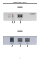
SENDER PANEL LAYOUT Front Panel 1 2 3 Back Panel 4 5 4 6
SENDER PANEL DESCRIPTIONS 1 Status LED This LED will become active once a stable link has been established between the sending and receiving units. 2 Power LED This LED will become active once the included power adapter has been connected. 3 Fiber Optic TX and RX Inputs Connect a LC terminated fiber optic cable for both the transmit (TX) and receive (RX) signals between the Firewire 800 sending and receiving units. 4 12V DC Power Supply Input Input for the supplied 12V DC power adapter.
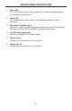
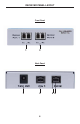
RECEIVER PANEL LAYOUT Front Panel 1 2 Back Panel 3 4 6 5 6
RECEIVER PANEL DESCRIPTIONS 1 Fiber Optic TX and RX Ports 1 Connect a LC terminated fiber optic cable for both the transmit (TX) and receive (RX) signals between the Firewire 800 sending and receiving units. Optionally, this port can be used for extension to another Receiving unit to extend the signal. 2 Fiber Optic TX and RX Ports 2 Connect a LC terminated fiber optic cable for both the transmit (TX) and receive (RX) signals between the Firewire 800 sending and receiving units.
CONNECTING AND OPERATING THE FIREWIRE 800 EXTENDER PLUS How to Connect the Firewire 800 Extender Plus 1. Connect the supplied Firewire cable from the computer’s Firewire port into one of the firewire ports on the Firewire 800 Extender Plus Sending unit. The other port can be used for a local Firewire device. 2. Connect one pair of LC terminated fiber optic cables from the Firewire 800 Extender Plus Sender unit to the Optical Port 1 on the Firewire 800 Extender Plus Receiving unit.
WIRING DIAGRAM Digital Video Camrecorder Firewire Extender Sender Fiber Optics Cable Firewire Extender Receiver CPU 9
SPECIFICATIONS Input Connector Type ................................................................................... 1394b Output Connector Type .................................................................................1394b Power Consumption Each Side .................................................... 36 Watts (max.) Power Supply ............................................................................................. 12VDC Dimensions ........................................................
11
Rev X1 20600 Nordhoff St., Chatsworth CA 91311 1-800-545-6900 818-772-9100 www.gefen.com fax: 818-772-9120 support@gefen.