GEFEN 4x4 HDMI MATRIX 4x4 Matrix for HDMI w/4 ELR-POL Outputs GEF-HDFST-444-4ELR User Manual www.gefenpro.
ASKING FOR ASSISTANCE Technical Support: Telephone Fax (818) 772-9100 (800) 545-6900 (818) 772-9120 Technical Support Hours: 8:00 AM to 5:00 PM Monday thru Friday, Pacific Time Write To: Gefen, LLC. c/o Customer Service 20600 Nordhoff St Chatsworth, CA 91311 www.gefenpro.com support@gefenpro.com Notice Gefen, LLC reserves the right to make changes in the hardware, packaging, and any accompanying documentation without prior written notice.
CONTENTS INTRODUCTION....................................................................................................................1 Features..........................................................................................................................2 Package Includes............................................................................................................2 Matrix Layout......................................................................................................
CONTENTS I/O Setup...............................................................................................................90 Preset Names...................................................................................................90 I/O Names.....................................................................................................91 HPD Control.................................................................................................92 FST.......................................
OPERATION NOTES READ THESE NOTES BEFORE INSTALLING OR OPERATING THE 4X4 MATRIX FOR HDMI W/4 ELR-POL OUTPUTS • EDID contains the A/V capabilities of a display device in regards to video resolutions and audio formats supported. This information is used by the source device to determine the format of the A/V signal on the outputs. The 4x4 Matrix for HDMI w/4 ELR-POL Outputs incorporates advanced EDID management to ensure compatibility with all sources and display devices. See pages 33 for more details.
INTRODUCTION Congratulations on your purchase of the GefenPRO 4x4 Matrix for HDMI w/4 ELR-POL Outputs. Your complete satisfaction is very important to us. GefenPRO In the realm of video distribution, certain features are invaluable in a commercial or broadcast environment. Accommodations such as a build-in power supply and flat black rack-mount enclosures set GefenPRO apart from our traditional products.
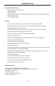
INTRODUCTION Supported HDMI Features • • • • • • Resolutions up to 1080p Full HD HDCP compliant 12-bit Deep Color LPCM 7.
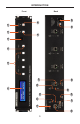
10 9 13 11 15 3 18 17 2 3 4 6 5 19 7 8 20 Front 14 12 16 GEFEN 4x4 HDMI MATRIX 1 INTRODUCTION Back
INTRODUCTION Front 1 LCD Display This is a two-line, sixteen-character display that shows status information and is also used to manage display / source routing. 2 Navigation Buttons Used for routing and adjusting settings of the 4x4 Matrix for HDMI w/4 ELR-POL Outputs. See the information beginning on page 13 for details on using these buttons. 3 Menu Press this button to display routing, switching mode, and IP address information. 4 IR Sensor Receives signals from the IR Remote Control.
INTRODUCTION Back 9 Grounding Terminal Provides a discharge path to ground in case a short circuit occurs between the “hot” lead of the power supply and the enclosure of the Matrix. The grounding wire should be attached from the grounding terminal to an approved ground path. 10 IP Control Connect an Ethernet cable to this port to control the 4x4 Matrix for HDMI w/4 ELR-POL Outputs using IP Control. See page 35 for more information on configuring the matrix for IP control.
INTRODUCTION Top Front 4 3 1 2 Back 6 5 6
INTRODUCTION Top / Front / Back 1 Power Indicator This LED indicator will glow bright blue when the matrix is powered and the ELR-POL Receiver unit is connected to the matrix using CAT-5e (or better) cable. 2 HDMI Out Connect an HDTV display to the HDMI Out port using an HDMI cable. 3 HDMI Locking Connector Used to lock the HDMI cable in place. 4 IR Out Connect an IR Emitter (Gefen part no. EXT-IREMIT) cable from this jack to the HDTV display. 5 IR Ext Connect an IR Extender (Gefen part no.
INTRODUCTION Layout and Description (RMT-16IRN) 1 2 1 LED Button Press Indicator This LED will be activated momentarily each time a button is pressed. 2 Display and Source Selection Buttons These buttons are used to select which source is routed to a display. The Source and Display buttons are mapped as follows: NOTE: An Activity Indicator that flashes quickly while holding down any one of the 16 buttons indicates a low battery. Replace the IR Remote Control battery as soon as possible.
INTRODUCTION Installing the Battery The Remote Control unit ships with two batteries (CR2032 lithium battery). One battery is required for operation and the other battery is a spare. 1. Remove the battery cover on the back of the IR Remote Control unit. 2. Insert the included battery into the open battery slot. The positive (+) side of the battery should be facing up. 3. Replace the battery cover.
CONNECTING THE 4X4 MATRIX FOR HDMI W/ 4 ELR-POL OUTPUTS How to Connect the 4x4 Matrix for HDMI w/4 ELR-POL Outputs 1. Connect up to four Hi-Def sources to the 4x4 Matrix for HDMI w/4 ELR-POL Outputs using HDMI cables. 2. Connect up to four HDTV displays to the supplied ELR-POL Receiver units using HDMI cables. 3. Connect each ELR-POL Receiver unit to the 4x4 Matrix for HDMI w/4 ELR-POL Outputs using CAT-5e (or better) cables.
OPERATING THE 4X4 MATRIX FOR HDMI W/ 4 ELR-POL OUTPUTS Main Display The Main Display of the 4x4 Matrix for HDMI w/4 ELR-POL Outputs is a 16-character 2-line display. This display shows the current routing status of the matrix and is also used to display additional system information. When the unit is powered on, the following screen is displayed: GEFEN 4x4 HDMI MATRIX After a few moments, the status screen is displayed.
OPERATING THE 4X4 MATRIX FOR HDMI W/ 4 ELR-POL OUTPUTS Determining the Current Routing State In the example below, the first row (OUT) represents each HDMI output on the matrix. The bottom row (IN) represents each HDMI input on the matrix. Together, these two rows display the current routing state. Starting on the bottom row, we can see that Input 3 has been routed to Output 1, Input 2 has been routed to Output 2, Input 1 has been routed to Output 3, and Input 4 has been routed to Output 4.
OPERATING THE 4X4 MATRIX FOR HDMI W/ 4 ELR-POL OUTPUTS Routing Sources Selecting the Output 1. To select the output, press the Out - or Out + button once. The routing state for Output A will be displayed. OUT:1 IN:3 2. Press the Out + button to cycle through each Output, from left to right. The Output with the currently routed Input will be displayed.
OPERATING THE 4X4 MATRIX FOR HDMI W/ 4 ELR-POL OUTPUTS 3. Consecutively pressing the Out - button will cycle through each output, from right to left. OUT: IN: 4 4 Changing the Source 4. Once the desired output has been selected, press the Input + or Input - button. Consecutively pressing the Input + button will increment the input value by a factor of 1 (within a range of 1 - 4).
OPERATING THE 4X4 MATRIX FOR HDMI W/ 4 ELR-POL OUTPUTS 5. Consecutively pressing the Input - button will decrease the input value by a factor of 1 (within a range of 1 - 4). For example, if Input 4 was originally routed to Output 4, pressing the Input - button will route Input 3 to Output 4. Source changed from Input 4 to Input 3. OUT: IN: 4 3 To change the routing status of another output, press the Output + or Output buttons to select the desired output.
OPERATING THE 4X4 MATRIX FOR HDMI W/ 4 ELR-POL OUTPUTS Locking / Unlocking the Front Panel To prevent an accidental routing change or power-down (by pressing the Lock button), the front-panel buttons on the 4x4 Matrix for HDMI w/4 ELR-POL Outputs can be locked. Locking the matrix also disables many RS-232 / Telnet commands. 1.
OPERATING THE 4X4 MATRIX FOR HDMI W/ 4 ELR-POL OUTPUTS FAST SWITCHING TECHNOLOGY Fast Switching Technology Fast Switching Technology (FST) is a Gefen software implementation for HDMI products. FST was created to improve the lengthy HDMI authentication process, based on the HDMI and HDCP specifications. FST provides quicker audio/video source switching and greatly improves the overall audio/ video system behavior and performance when more than one HDTV display is used in the system setup.
OPERATING THE 4X4 MATRIX FOR HDMI W/ 4 ELR-POL OUTPUTS Determining the Current Switching Mode Each HDMI input can be set to Fast Mode or Slow Mode. It is recommended that each HDMI input be set to Fast Mode for best performance. 1. Consecutively press the Menu button on the front panel until the switching modes screen is displayed. The first row (IN) represents each HDMI input on the matrix. The bottom row (MODE) represents the current switching mode of each HDMI input.
OPERATING THE 4X4 MATRIX FOR HDMI W/ 4 ELR-POL OUTPUTS 3. Press the Output - or Output + button again to cycle through the routing state for each output. Consecutively pressing the Output + button will cycle through each input, from left to right, starting with Input 1: NOTE: In Routing mode, the Output + and Output - buttons cycle through each output. In Switching mode, these same buttons are used to cycle through each input. IN: MODE: 4.
OPERATING THE 4X4 MATRIX FOR HDMI W/ 4 ELR-POL OUTPUTS Changing the Switching Mode 5. Once the desired input has been selected, press the Input + or Input - button to toggle between Fast or Slow switching mode. Switching mode changed from Slow to Fast on Input 2. IN: 2 MODE: F To change the switching mode of another input, press the Output + or Output button to navigate to the desired input. Press the Input + or Input - button to toggle the switching mode between Fast (F) or Slow (S). 6.
OPERATING THE 4X4 MATRIX FOR HDMI W/ 4 ELR-POL OUTPUTS Setting the IR Channel In order for the 4x4 Matrix for HDMI w/4 ELR-POL to communicate with the included IR Remote Control, both the matrix and the IR Remote Control must be set to the same IR channel. Follow the procedure outlined below to set the IR channel on the 4x4 Matrix for HDMI w/4 ELR-POL. 1. From the Routing screen, simultaneously press the Input - , Input +, and the Output - buttons to display the IR address screen.
OPERATING THE 4X4 MATRIX FOR HDMI W/ 4 ELR-POL OUTPUTS 3. After setting the IR address, make sure that the DIP switches on the IR Remote Control are set according to the information in the LCD display. See page 9 for information on setting the IR channel for the IR Remote Control unit. IR ADDRESS : 1 1-ON , 2-OFF In the example above, the 4x4 Matrix for HDMI w/4 ELR-POL is set to IR channel 1.
OPERATING THE 4X4 MATRIX FOR HDMI W/ 4 ELR-POL OUTPUTS Routing Sources using the IR Remote Control The included IR Remote Control unit provides discrete switching for each output. The IR remote control unit consists of 16 buttons. Buttons are color-coded and arranged in groups of four. There are a total of four outputs on the matrix. The first set of buttons on the IR remote represent Output 1. The second set of four buttons represent Output 2, and so on.
OPERATING THE 4X4 MATRIX FOR HDMI W/ 4 ELR-POL OUTPUTS Bi-Directional IR The Bi-Directional IR feature allows two simultaneous methods of control: Control of the source device / matrix and control of the display. Each source device can be controlled from the viewing location by connecting an IR Extender (Gefen part no. EXT-RMT-EXTIR) to each Receiver unit. The display is controlled by connecting a PACS / Mini PACS to the matrix.
OPERATING THE 4X4 MATRIX FOR HDMI W/ 4 ELR-POL OUTPUTS Refer to page 10 and make sure all remaining connections are made between the matrix and all source and display devices. Controlling the Source from the viewing location Receiver unit Point the source’s IR remote control at the IR Extender. The illustration below shows how the source, connected to HDMI In 1, is controlled from the Receiver unit (viewing location). IR signals are transmitted over the CAT-5 cable to the matrix.
OPERATING THE 4X4 MATRIX FOR HDMI W/ 4 ELR-POL OUTPUTS Switching between Sources Receiver unit Matrix switching can also be controlled by using the same setup. Use the included IR remote control (Gefen part no. RMT-16IRN) to switch between sources. In the example below, the source connected to HD In 2 has been routed to the Receiver unit connected to Out A. See page 23 for details on routing sources using the included IR remote control.
OPERATING THE 4X4 MATRIX FOR HDMI W/ 4 ELR-POL OUTPUTS Controlling the Display Displays can also be controlled by connecting the Gefen PACS (or Mini PACS) to the matrix. Connect up to four 3.5mm-to-3.5mm mini-mono cables from the IR Emitter outputs on the Gefen PACS (or Mini PACS) to the respective IR In ports on the matrix. The red arrows indicate IR signals from the PACS / Mini PACS. Gefen PACS To local network CAT-5 To Receiver unit Matrix 1.
OPERATING THE 4X4 MATRIX FOR HDMI W/ 4 ELR-POL OUTPUTS Receiver unit Connect an IR Emitter from each IR Out jack, on the Receiver unit, to the IR sensor on the HDTV display. HDMI cable IR signals HDTV display 2. IR Emitter Each display can now receive IR commands from the PACS or Mini PACS. Refer to the PACS or Mini PACS User Manual for more information on using IR commands.
OPERATING THE 4X4 MATRIX FOR HDMI W/ 4 ELR-POL OUTPUTS IR Broadcasting to Sources In addition to sending IR commands to a single source, the 4x4 Matrix for HDMI w/ 4 ELRPOL Outputs also allows IR commands to be broadcast to all source devices. Receiver unit Connect an IR Extender to the IR Ext jack on each Receiver unit. Each of the Receiver units should already be connected to their respective CAT-5 outputs on the matrix. See the next page for more information on this type of setup.
OPERATING THE 4X4 MATRIX FOR HDMI W/ 4 ELR-POL OUTPUTS In the illustration on the previous page, the source remote is being used to send IR commands to the source device. The IR Blaster will broadcast the IR command(s) to all source devices in the room (or within the range of the IR Blaster). This feature has many useful applications. For example, let’s say we have four Sony Blu-ray players connected and we want to send a “play” command to these source devices.
OPERATING THE 4X4 MATRIX FOR HDMI W/ 4 ELR-POL OUTPUTS IR Broadcasting to Displays In addition to sending IR commands to a single display, the 4x4 Matrix for HDMI w/ 4 ELRPOL Outputs also allows IR commands to be broadcast to all displays devices. Connect a 3.5mm-to-3.5mm mini-mono cable from one of the IR Emitter outputs on the Gefen PACS to the IR In All port on the matrix. Gefen PACS To local network CAT-5 To Receiver unit Matrix 1.
OPERATING THE 4X4 MATRIX FOR HDMI W/ 4 ELR-POL OUTPUTS Receiver unit Connect an IR Emitter from each IR Out jack, on the Receiver unit, to the IR sensor on the HDTV display. HDMI cable IR signals HDTV display 2. IR Emitter When an IR command is sent from the Gefen PACS / Mini PACS, the command will be sent to every Receiver unit that is connected to the matrix. This operation occurs independently of the current routing status. This feature has many applications.
OPERATING THE 4X4 MATRIX FOR HDMI W/ 4 ELR-POL OUTPUTS External EDID Management The 4x4 Matrix for HDMI w/4 ELR-POL features EDID Management. Before the source can send video or audio signals, the source device reads the EDID (Extended Display Identification Data) from the output devices connected to the matrix. The EDID contains information about what type of audio/video data that the source can send to each output device.
RS-232 / IP CONTROL RS-232 Interface 5 4 3 2 1 DE-9 6 7 8 9 DA-15 RS-232 Controller Matrix DCD 1 1 DCD RXD 2 2 RXD TXD 3 3 TXD DTR 4 4 DTR GND 5 5 DSR 6 6 RTS 7 7 CTS 8 8 CTS R1 9 9 R1 Only TXD, RXD, and GND are used. DB-25 GND DSR RTS DC-37 RS232 Settings Baud rate .......................................................................................................................19200 Data bits ..............................................................
RS-232 / IP CONTROL Configuring the IP Address The 4x4 Crosspoint Matrix for HDMI supports IP-based control using the built-in Web GUI and Telnet protocol. To set up Telnet control, the network settings for the matrix must be configured via RS-232. The default network settings for the matrix are as follows: 192.168.1.72 255.255.255.0 192.168.1.254 80 23 IP Address: Subnet: Gateway: HTTP Port: Telnet Port: 1. Connect an RS-232 cable from the PC to the matrix. 2. Launch a terminal emulation program (e.
RS-232 / IP CONTROL IP / Telnet Configuration Command Description #display_telnet_welcome Set Telnet welcome message on login #ipconfig Displays all TCP/IP settings #resetip Resets IP configuration to factory settings #set_http_port Sets the Web server listening port #set_telnet_pass Prompts for password when using Telnet #set_telnet_port Sets the Telnet listening port #set_webui_ad_pass Sets the Web UI administrator password #set_webui_op_pass Sets the Web UI operator password #sgateway
RS-232 / IP CONTROL #display_telnet_welcome Command The #display_telnet_welcome command enables or disables the Telnet welcome message on login. Syntax: #display_telnet_welcome param1 Parameters: param1 Value [0 ... 1] Value Description 0 Do not display welcome message 1 Display welcome message Example: #display_telnet_welcome 1 #Telnet Welcome Screen is Enable #ipconfig Command The #ipconfig command displays the current TCP/IP settings for the matrix.
RS-232 / IP CONTROL #resetip Command The #resetip command resets all TCP/IP settings to factory defaults. Syntax: #resetip Parameters: None Notes: The matrix must be rebooted after executing this command. Example: #resetip IP Configuration Was Reset To Factory Defaults. After rebooting the matrix, the IP settings will be cleared. Running the #ipconfig command will display the updated information: #ipconfig IP: 192.168.1.120 NETMASK: 255.255.255.0 GATEWAY: 192.168.1.
RS-232 / IP CONTROL #set_http_port Command The #set_http_port command sets the Web server listening port. The default port setting is 80. Also see the #show_http_port on page 45. Syntax: #set_http_port param1 Parameters: param1 Port [0 ... 1024] Notes: The matrix must be rebooted after executing this command. Example: #set_http_port 80 HTTP Communication Port 80 Is Set. Please Reboot The Unit.
RS-232 / IP CONTROL #set_telnet_pass Command The #set_telnet_pass command sets the Telnet password. The maximum length of the password is 20 characters. The password is case-sensitive. The default Telnet password is Admin. Syntax: #set_telnet_pass param1 Parameters: param1 Password [20 chars max.] Notes: The matrix must be rebooted after executing this command. Example: #set_telnet_pass reindeer TELNET Interface Password Is Set.
RS-232 / IP CONTROL #set_telnet_port Command The #set_telnet_port command sets the Telnet listening port. The default port value is 23. Syntax: #set_telnet_port param1 Parameters: param1 Port [0 ... 1024] Notes: The matrix must be rebooted after executing this command. Example: #set_telnet_port 23 Telnet Communication Port 23 Is Set. 41 Please Reboot The Unit.
RS-232 / IP CONTROL #set_webui_ad_pass Command The #set_webui_ad_pass command sets the Administrator password for the Web interface. The maximum length of the password is 8 characters. Syntax: #set_webui_ad_pass param1 Parameters: param1 Password [8 chars max.] Notes: The matrix must be rebooted after executing this command. Example: #set_webui_ad_pass Everest Web UI Administrator Password Is Set.
RS-232 / IP CONTROL #set_webui_op_pass Command The #set_webui_op_pass command sets the Operator password for the Web interface. The maximum length of the password is 8 characters. Syntax: #set_webui_op_pass param1 Parameters: param1 Password [8 chars max.] Notes: The matrix must be rebooted after executing this command. Example: #set_webui_op_pass Denali Web UI Operator Password Is Set.
RS-232 / IP CONTROL #sgateway Command The #sgateway sets the gateway (router) address. Dot-decimal notation must be used when specifying the gateway address. The default gateway address is 192.168.1.254. Syntax: #sgateway param1 Parameters: param1 Gateway address Notes: The matrix must be rebooted after executing this command. Example: #sgateway 192.168.2.1 GateWay Address 192.168.2.1 Is Set. Please Reboot The Unit. #show_gateway Command The #show_gateway command shows the current gateway address.
RS-232 / IP CONTROL #show_http_port Command The #show_http_port command displays the current HTTP listening port. Syntax: #show_http_port Parameters: None Example: #show_http_port HTTP COMMUNICATION PORT IS: 80 #show_ip Command The #show_ip command shows the current IP address of the Matrix. Syntax: #show_ip Parameters: None Example: #show_ip IP ADDRESS IS: 192.168.1.
RS-232 / IP CONTROL #show_mac_addr Command The #show_mac_addr command displays the MAC address of the Matrix. Syntax: #show_mac_addr Parameters: None Example: #show_mac_addr MAC ADDRESS IS: 00-12-0e-f1-7a-ea #show_netmask Command The #show_netmask displays the netmask address. Syntax: #show_netmask Parameters: None Example: #show_netmask NET MASK ADDRESS IS: 255.255.255.
RS-232 / IP CONTROL #show_telnet_port Command The #show_telnet_port command displays the current Telnet listening port. Syntax: #show_telnet_port Parameters: None Example: #show_telnet_port TELNET COMMUNICATION PORT IS: 23 #show_telnet_username Command The #show_telnet_username command returns the user name required for login.
RS-232 / IP CONTROL #show_ver_data Command The #show_ver_data command displays the hardware and firmware version of the Matrix. Syntax: #show_ver_data Parameters: None Example: #show_ver_data SOFTWARE AND HARDWARE VERSION: v3.0K PCB-1707*B #show_webui_username Command The #show_webui_username command displays the current user name required for login.
RS-232 / IP CONTROL #sipadd Command The #sipadd command sets the IP address of the matrix. Dot-decimal notation must be used when specifying the IP address. Syntax: #sipadd param1 Parameters: param1 IP address Notes: The matrix must be rebooted after executing this command. Example: #sipadd 192.168.1.238 IP Address 192.168.1.238 Is Set. Please Reboot The Unit.
RS-232 / IP CONTROL #snetmask Command The #snetmask command sets the IP network subnet mask. Dot-decimal notation must be used when specifying the IP network mask. The default subnet mask is: 255.255.255.0 Syntax: #snetmask param1 Parameters: param1 Subnet mask Notes: The matrix must be rebooted after executing this command. Syntax: #snetmask 255.255.0.0 NetMask Address 255.255.0.0 Is Set. 50 Please Reboot The Unit.
RS-232 / IP CONTROL #use_telnet_pass Command The #use_telnet_pass command requires or disables Telnet login credentials. The default setting is disabled (param1 = 0). Syntax: #use_telnet_pass param1 Parameters: param1 State [0 ...
RS-232 / IP CONTROL Routing / Naming / Presets Command Description #lock_matrix Locks / unlocks the Matrix #recall_preset Recalls a routing / mask preset #save_preset Saves the current routing/masking state to a preset #set_bank_name Names the specified EDID bank #set_input_name Specifies a name for an input #set_output_name Specifies a name for an output #set_preset_name Names the specified preset #show_bank_name Displays the name of the specified bank #show_input_name Displays the speci
RS-232 / IP CONTROL #lock_matrix Command The #lock_matrix command locks / unlocks the Matrix. When the Matrix is locked, all functions are disabled including the front panel, RS-232, and Telnet. Syntax: #lock_matrix param1 Parameters: param1 Value [0 ... 1] Value Description 0 Unlock Matrix 1 Lock Matrix Example: #lock_matrix 1 MATRIX IS LOCKED #recall_preset Command The #recall_preset command recalls a routing preset. Any masked outputs will also be recalled.
RS-232 / IP CONTROL #save_preset Command The #save_preset command saves the current routing state to the specified preset. Any masked outputs will also be saved as part of the current routing state. Syntax: #save_preset param1 Parameters: param1 Preset [1 ... 8] Example: #save_preset 1 CURRENT ROUTING STATE IS SAVED TO PRESET/INPUT 1 #set_bank_name Command The #set_bank_name command names the specified EDID bank. Syntax: #set_bank_name param1 Parameters: param1 Bank [1 ...
RS-232 / IP CONTROL #set_input_name Command The #set_input_name command provides a name to the selected input. For example, “Input 1” could be renamed as “DVD_Player”. Syntax: #set_input_name param1 param2 Parameters: param1 Input [1 ... 4] param2 Name [15 chars max.] Example: #set_input_name 4 Blu-ray Blu_ray NAME IS ASSIGNED TO INPUT 5 #set_output_name Command The #set_output_name command provides a name to the selected output. For example, “Output 1” could be renamed as “HDDisplay”.
RS-232 / IP CONTROL #set_preset_name Command The #set_preset_name command assigns a preset with the specified name. Syntax: #set_preset_name param1 Parameters: param1 Preset [1 ... 8] param2 Name [20 chars max.] Example: #set_preset_name 6 monitor_booth monitor_booth NAME IS ASSIGNED TO PRESET 6 #show_bank_name Command The #set_bank_name command displays the specified EDID bank name. Syntax: #show_bank_name param1 Parameters: param1 Bank [1 ...
RS-232 / IP CONTROL #show_input_name Command The #show_input_name command displays the specified input name. Syntax: #show_input_name param1 Parameters: param1 Input [1 ... 8] Example: #show_input_name 4 THE NAME FOR INPUT 4 IS: Blu-ray #show_output_name Command The #show_output_name command displays the name of the specified output. Syntax: #show_output_name param1 Parameters: param1 Output [1 ...
RS-232 / IP CONTROL #show_preset_name Command The #show_preset_name command displays the name of the specified preset. Syntax: #show_preset_name param1 Parameters: param1 Preset [1 ... 8] Example: #show_preset_name 6 THE NAME FOR PRESET 6 IS: monitor_booth #show_r Command The #show_r command shows the current routing status of the specified output. The underscore character (“_”) must be included when typing the command name. Syntax: #show_r param1 Parameters: param1 Output [1 ...
RS-232 / IP CONTROL r Command The r command routes the specified input to the specified outputs. Do not precede the r command with the “#’ symbol. Syntax: r param1 param2[...param9] Parameters: param1 Input [1 ... 4] param2 Outputs [1 ... 4] Notes: If param2 = 0, then the specified input is routed to all outputs. See the s command on the following page. Examples: r 4 1 2 3 INPUT 4 IS SET TO OUTPUTS 1, 2, 3 r 2 0 INPUT 4 IS SET TO ALL OUTPUTS.
RS-232 / IP CONTROL s Command The s command routes the specified input to all outputs. Do not precede the s command with the “#’ symbol. Syntax: s param1 Parameters: param1 Input [1 - 8] Examples: s 2 INPUT 2 IS SET TO ALL OUTPUTS.
RS-232 / IP CONTROL Status Command Description #help Displays all available commands #show_fw Displays the Matrix firmware version #show_hpd Displays the HPD status of the specified output #show_rsense Displays the RSENSE status of the specified output m Displays the current matrix routing status in table format n Displays the routing status for the specified output #help Command The #help command displays help on the specified command.
RS-232 / IP CONTROL #show_fw Command The #show_fw command displays the current firmware version of the Matrix. Syntax: #show_fw Parameters: None Example: #show_fw FIRMWARE VERSION = GEF-HDFST-444-4ELR v3.0K #show_hdp Command The #show_hpd command displays the HPD (Hot-Plug Detect) status of the specified output. The underscore character (“_”) must be included when typing the command name. Syntax: #show_hpd param1 Parameters: param1 Output [1 ...
RS-232 / IP CONTROL #show_rsense Command The #show_rsense command displays Rsense status of the specified output. Syntax: #show_rsense param1 Parameters: param1 Output [1 ... 4] Notes: The alternate name of the output (see the #set_output_name command) will be displayed in parentheses, next to the physical name of the output.
RS-232 / IP CONTROL m Command The m command displays the current matrix routing status in tabular format. Do not precede this command with the “#’ symbol.
RS-232 / IP CONTROL n Command The n command displays the current input-output routing state for the specified output. Do not precede this command with the “#’ symbol. Syntax: n param1 Parameters: param1 Output [1 ... 4] Notes: If param1 = 0, then the routing status for all outputs will be displayed. In the second example, n 0 returns the routing state for all Outputs. Examples: The return result is read as pairs of numbers. The first number is the output and the second number is the input.
RS-232 / IP CONTROL FST Command Description #fst_fast Sets the specified inputs to Fast switching mode #fst_slow Sets the specified inputs to Slow switching mode #show_fst Displays the current switching mode for the specified input #fst_fast Command The #fst_fast command sets the specified inputs to Fast switching mode. Syntax: #fst_fast param1 Parameters: param1 Input [1 ... 4] Notes: If param1 = 0, then all inputs will be set to Fast switching mode.
RS-232 / IP CONTROL #fst_slow Command The #fst_slow command sets the specified inputs to Slow switching mode. Syntax: #fst_slow param1 Parameters: param1 Input [1 ... 4] Notes: If param1 = 0, then all inputs will be set to Slow switching mode. Example: #fst_slow 1 INPUT 1 IS SET TO FST SLOW MODE #show_fst Command The #fst_slow command sets the specified inputs to Slow switching mode. Syntax: #show_fst param1 Parameters: param1 Input [1 ...
RS-232 / IP CONTROL Masking Command Description #echo Enables / disables RS-232 feedback #fadefault Resets the matrix to factory defaults #hdcp Disables HDCP on the specified input #hpd_pulse Cycles the HPD line on the specified input #lock_edid Locks the local EDID when powering the matrix #mask Masks the specified outputs #power Powers the matrix on or off #reboot Reboots the matrix #set_edid Copies EDID data between inputs, outputs, and banks #set_ir Sets the IR channel of the matrix
RS-232 / IP CONTROL #echo Command The #echo command enables / disables serial port (terminal) echo when typing command. However, any command feedback will always be displayed.
RS-232 / IP CONTROL #fadefault Command The #fadefault command disables the EDID lock state, sets the default routing state (1-1, 2-2, 3-3, etc.), and resets the input and output names to the default names (e.g. Output 1, Input 1).
RS-232 / IP CONTROL #hdcp Command The #hdcp command disables HDCP on the selected input. NOTE: Some computers will enable HDCP if an HDCP-compliant display is detected. Set param2 = 1 to force the computer to ignore detection of an HDCP-compliant display. Note that using this command does not decrypt HDCP content. Syntax: #hdcp param1 param2 Parameters: param1 Input [1 ... 4] param2 Value [0 ...
RS-232 / IP CONTROL #hpd_pulse Command The #hpd_pulse command cycles the HPD line on the specified input. Issuing this command is identical to physically disconnecting and reconnecting the cable between the source and the matrix. Syntax: #hpd_pulse param1 Parameters: param1 Input [1 ... 4] Notes: Set param1 = 0 to cycle the HPD line on all inputs.
RS-232 / IP CONTROL #lock_edid Command The #lock_edid command secures the Local EDID by disabling the automatic loading of the downstream EDID after the matrix is powered. Syntax: #lock_edid param1 Parameters: param1 Value [0 ...
RS-232 / IP CONTROL #mask Command The #mask command masks the specified outputs. Syntax: #mask param1[...param4] Parameters: param1 Output [1 ... 4] Notes: If param1 = 0, then all outputs are masked.
RS-232 / IP CONTROL #power Command The #power command toggles the power state on the matrix. Syntax: #power param1 Parameters: param1 Value [0 ... 1] Value Description 0 Power matrix OFF 1 Power matrix ON Notes: Each time the matrix is powered, the current routing status will be echoed to the terminal.
RS-232 / IP CONTROL #reboot Command The #reboot command reboots the matrix. Syntax: #reboot Parameters: None Notes: Each time the matrix is rebooted, the current routing status will be echoed to the terminal. Example: #reboot MATRIX WILL REBOOT SHORTLY *REBOOT UNIT IN 2 SECONDS GEF-HDFST-444-4ELR v3.
RS-232 / IP CONTROL #set_edid Command The #set_edid command sets the specified EDID type to an input or bank. Syntax: #set_edid param1 param2 param3 param4 Parameters: param1 param2 param3 param2 Source type [STRING] String Description default Uses default EDID dynamic Uses Dynamic EDID bank Uses EDID bank output Uses EDID on Output (sink) Source number Value Description 0 Default EDID 1 ... 8 EDID Bank 1 ... 4 Output Target type [0 ...
RS-232 / IP CONTROL Notes: If param1 = default or param1 = dynamic, set param2 = 0. Using Dynamic EDID When param1 = dynamic, the specified input will be set to Dynamic EDID. This can be observed by accessing the Manage EDID tab, in the Web interface (see page 92). When an input is set to Dynamic EDID, the input will use the EDID of the last selected output during the routing process. The order in which outputs are routed are important when using Dynamic EDID. See the example below.
RS-232 / IP CONTROL #set_ir Command The #set_ir set the IR channel for the matrix. The associated DIP switch settings for the IR remote control unit are returned. See page 9 for details on setting the IR channel for the IR remote control. Syntax: #set_ir param1 Parameters: param1 Channel [0 ... 3] Example: #set_ir 0 IR CHANNEL IS SET TO CHANNEL 0 #show_ir Command The #show_ir displays the current IR channel for the matrix.
RS-232 / IP CONTROL #show_hdcp Command The #show_hdcp command displays the HDCP status on the specified input Syntax: #show_hdcp param1 Parameters: param1 Input [1 ... 4] Notes: Set param1 = 0 to displays the HDCP status of all inputs.
RS-232 / IP CONTROL #show_mask Command The #show_mask command displays the mask status for the specified output. Syntax: #show_mask param1 Parameters: param1 Output [1 ... 4] Example: #show_mask 4 OUTPUT 4(OUTPUT4) IS UNMASKED #show_out_colordpt Command The #show_out_colordpt command displays the highest color depth supported by the specified display based on the EDID. The underscore characters (“_”) must be included when typing the command name.
RS-232 / IP CONTROL #show_out_res Command The #show_out_res command displays the highest resolution supported by the specified display based on the EDID. Syntax: #show_out_res param1 Parameters: param1 Output [1 ...
RS-232 / IP CONTROL #unmask Command The #unmask command unmasks the specified outputs. Syntax: #unmask param1[...param9] Parameters: param1 Output [1 ... 4] Notes: If param1 = 0, then all outputs are unmasked.
RS-232 / IP CONTROL Using the Built-in Web server The Web GUI is divided into four main pages: Main, I/O Setup, Manage EDID, and Configuration. Each main page is represented by a tab at the top-most portion of the screen. The Main, I/O Setup, and Manage EDID pages have their own set of sub-tabs. Click on the desired tab / sub-tab to open the desired page. When the Web GUI is opened in a Web browser, the Main page / tab will be displayed.
RS-232 / IP CONTROL Lock Matrix Locks / unlocks the matrix. When the matrix is locked, no modifications can be made using the Web GUI. When the matrix is locked, the button text will read “Unlock Matrix” and a red bar will appear across the top portion of the screen with the text “Matrix is LOCKED”. Click the “Unlock Matrix” button to unlock the matrix. See the illustration at the bottom of the page. Legend Provides color-coded information on the status of each Input and Output.
RS-232 / IP CONTROL Name Displays the current name of each output. The name of each input can be changed. Refer to the #set_input_name command on page 55 for details on naming inputs. Output Click to place a check mark in the box and select the desired output. Multiple outputs can be selected at a time. Check All Places a check mark in each box under the Output # column. Route Click this button to route the current input and output selection(s).
RS-232 / IP CONTROL Save Routing Preset Saves the current routing state to memory. Click the drop-down list to select the desired routing preset, then click the Save button to save the preset to memory. Recall Routing Preset Loads the selected routing state into memory. Click the desired button to load the desired routing preset into memory.
RS-232 / IP CONTROL Main >> I/O Status Output Displays the state of each output for each of the following: Output name, RSENSE, Mask, HPD (Hot-Plug Detect), HDCP, and POL. Input Displays the state of each input for each of the following: Input name, Color Depth, Color Space, HDCP, 3D, Active Signal, Vertical Resolution, Horizontal Resolution, Progressive / Interlaces, and Refresh Rate.
RS-232 / IP CONTROL Main >> Display Info Choose EDID Select the EDID from the drop-down list. The selected EDID will be copied from the selected EDID Bank or Output to the desired input(s) and used by the source. Options: Default EDID, Bank 1 ... Bank 8, Output 1 ... Output 4 Feature / Audio Formats Displays the capabilities of the display (or sink device), based on the EDID.
RS-232 / IP CONTROL I/O Setup >> Preset Names Name Type the desired name of the Preset in this field. Click the Save Changes button to save the Preset Name. Click the Cancel button to restore the previous name. Save Changes Saves the current changes. Cancel Restores the previous names for each Preset, if a change was made.
RS-232 / IP CONTROL I/O Setup >> I/O Names Save Changes Saves the current changes. Cancel Restores the previous names for each Preset, if a change was made. Name Type the desired name of each Output or Input in these fields. Click the Save Changes button or click the Cancel button to restore the previous name.
RS-232 / IP CONTROL I/O Setup >> HPD Control Pulse Click the Pulse button to cycle the HPD line on the desired input. This is the equivalent of physically disconnecting and reconnecting the HDMI cable between the source device and the matrix.
RS-232 / IP CONTROL I/O Setup >> FST Check All Places a check mark in each box under the FST column. Clear All Clears all check marks from the FST column. Set Click this button to enable FST on the selected input(s). The Web GUI will display a prompt to verify the selected operation. Cancel Restores the previous FST state for each input, if a change was made. FST Click to select the desired input(s). Selecting the input does not automatically enable the FST feature.
RS-232 / IP CONTROL I/O Setup >> HDCP NOTE: Some computers will enable HDCP if an HDCP-compliant display is detected. Use the Disable feature to force the computer to ignore detection of an HDCP-compliant display. Note that using the Disable feature does not decrypt HDCP content. Check All Places a check mark in each box under the HDCP column. Clear All Clears all check marks from the HDCP column. Set Click this button to disable HDCP on the selected input(s).
RS-232 / IP CONTROL Manage EDID >> Assign Lock EDID Secures the Local EDID and disables the automatic loading after power-up. See the #lock_edid command on page 70 for more information. Copy EDID From Select the EDID from the drop-down list. The EDID will be copied from the selected destination to the desired input or EDID bank. Options: Default EDID, Bank 1 ... Bank 8, Output 1 ...
RS-232 / IP CONTROL Copy To Click to select the desired input(s). EDID Modes Click the drop-down list to select the EDID mode. Check All Places a check mark in each box under the Copy To column. Clear All Clears all check marks from the Copy To column. Options: Custom, Last Output If the EDID Mode is set to Last Output, then the EDID source will be set to Dynamic EDID. See page 75 for details on using Dynamic EDID.
RS-232 / IP CONTROL Copy To Click this button to copy the specified EDID to the selected inputs / banks. Check All Places a check mark in each box under the Copy To column. Clear All Clears all check marks from the Copy To column. 97 Cancel Restores the previous EDID state for each input, if a change was made.
RS-232 / IP CONTROL Manage EDID >> Bank Names Bank # Indicates the EDID bank number. Name Type the desired name of the EDID bank in this field. Click the Save Changes button to save the bank name. Click the Cancel button to restore the previous name. Save Changes Saves the current name change to the EDID bank(s). Cancel Restores the previous names for each EDID bank, if a change was made.
RS-232 / IP CONTROL Manage EDID >> Upload / Download Upload Click this button to upload the EDID to the specified bank. Select Bank Location Click this drop-down list to select the bank to where the EDID will be uploaded. Options: Bank 1 ... Bank 8 Drop-down list Click this box to select the EDID that is to be saved to a file. The EDID file will be saved in binary format (.bin). Options: Bank 1 ... Bank 8, Output 1 ... Output 4, Input 1 ... Input 4 99 Browse...
RS-232 / IP CONTROL Configuration >> Change IP Settings Change IP Settings Assigns IP address, subnet, gateway, HTTP listening port, and Telnet port. The MAC address cannot be changed. Save Settings Saves the current settings for the Change IP Settings. After clicking this button, the Web interface will display a dialog indicating that the matrix must be rebooted for changes to take effect. Set Defaults Click this button to restore the factory-default IP settings.
RS-232 / IP CONTROL Configuration >> Telnet Login Settings Old Password Type the current (old) password in this field. New Password Type the new password in this field. Force Password on Connect Click this check box to have the matrix prompt for a password each time a Telnet session is started. Show Login Message on Connect Click this check box to have the matrix display the Telnet welcome message each time a Telnet session is started.
RS-232 / IP CONTROL Configuration >> Web Login Settings Username Click this drop-down list to select the username to be changed. Old Password Type the current (old) password in this field. New Password Type the new password in this field. Confirm Password Re-type the new password in this field. Save Settings Saves the current changes to the Web Login Settings.
RS-232 / IP CONTROL Configuration >> System Configuration Download Current Configuration Click this button to download the current configuration to a file.
RS-232 / IP CONTROL Browse Click this button to select the firmware file to be uploaded. See page 101 for details on updating the firmware. Browse Click this button to select the saved configuration file to be loaded into memory. Restore Uploads the selected configuration file to the matrix. Update Updates the matrix with the selected firmware file. Reset Click this button to set the matrix to factory-default settings. The IP settings are preserved. Reboot Click this button to reboot the matrix.
APPENDIX Firmware Update Procedure 1. Make sure the 4x4 Matrix for HDMI is powered. 2. Connect an Ethernet cable between the matrix and the computer running the Web GUI. 3. Go to the Configuration tab in the Web GUI and click the Browse... button under the System Configuration section. 4. Select the firmware file and click the Update button 5. The matrix will prompt you to verify that you want to overwrite the current firmware.
RACK MOUNT SAFETY INFORMATION a. Maximum recommended ambient temperature: 45 ˚C (104 ˚F). b. Increase the air flow as needed to maintain the recommended temperature inside the rack. c. Do not exceed maximum weight loads for the rack. Install heavier equipment in the lower part of the rack to maintain stability. d. Connect a bonding wire between an approved safety ground and the grounding screw on the chassis.
SPECIFICATIONS Maximum Pixel Clock................................................................................................ 225 MHz ELR extension range.................................................................... Up to 330 feet (100 meters) Matrix Video Input Connectors................................. (4) HDMI Type A 19-pin, female, locking Matrix Video Output Connectors................................................... (4) ELR-POL RJ45, female Receiver ELR-POL Input Connector...............
WARRANTY Gefen warrants the equipment it manufactures to be free from defects in material and workmanship. If equipment fails because of such defects and Gefen is notified within two (2) years from the date of shipment, Gefen will, at its option, repair or replace the equipment, provided that the equipment has not been subjected to mechanical, electrical, or other abuse or modifications.
LICENSING lwIP is licenced under the BSD licence: Copyright (c) 2001-2004 Swedish Institute of Computer Science. All rights reserved. Redistribution and use in source and binary forms, with or without modification, are permitted provided that the following conditions are met: 1. Redistributions of source code must retain the above copyright notice, this list of conditions and the following disclaimer. 2.
Rev A1 20600 Nordhoff St., Chatsworth CA 91311 1-800-545-6900 818-772-9100 www.gefenpro.com Pb fax: 818-772-9120 support@gefenpro.