
User manual


3. Once the LED under column 2 is enabled, a picture will be displayed on the
display connected to Out 3 on the matrix.
Note that in Fig1.1, Out 1, Out 2, and Out 4 have also been routed. In this
case, the displays connected to HDMI Out 1, HDMI Out 2, and HDMI Out 3 are
receiving video from the source connected to HDMI In 1.
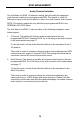
Example 2: Routing Input (source) 3 to Output (display) 1
Using Fig1.1 as a starting point, press the Out 1 button two (2) times. The LED
matrix should now appear as follows:
Fig1.2
LED 3 is enabled on the row labeled Out 1, indicating that Output (display) 1 is
connected to the source on HDMI In 3.
In Fig.1.2, the current state of the matrix is: Display 1 is viewing Source 3,
Display 2 is viewing Source 1, Display 2 is viewing Source 2, and Display 4 is
viewing Source 1. Note that both Display 2 and Display 4 are viewing the same
source.