Mini PACS GTB-MINI-PACS User Manual www.gefentoolbox.
ASKING FOR ASSISTANCE Technical Support: Telephone (818) 772-9100 (800) 545-6900 Fax (818) 772-9120 Technical Support Hours: 8:00 AM to 5:00 PM Monday through Friday, Pacific Time Write To: Gefen, LLC c/o Customer Service 20600 Nordhoff St Chatsworth, CA 91311 www.gefentoolbox.com support@gefentoolbox.com Notice Gefen, LLC reserves the right to make changes in the hardware, packaging and any accompanying documentation without prior written notice.
CONTENTS 1 2 3 4 5 6 6 7 12 12 13 14 15 17 22 26 30 32 33 33 35 36 37 39 41 43 43 56 63 74 77 77 78 80 81 Introduction Operation Notes Features Panel Layout Panel Descriptions Connecting the Mini PACS Wiring Diagram Configuring the IP Address Web Interface The Built-in Web Server RS-232 Menu RS-232 Settings TCP / UDP Bridge Settings IR Emitters Menu Adding a new IR device Adding a new IR device from a Template Relays Menu Testing Relays Configuration Menu IP Configuration Telnet Login Settings Firmware Upd
INTRODUCTION Congratulations on your purchase of the Mini Professional Automation Control System. Your complete satisfaction is very important to us. Gefen Gefen delivers innovative, progressive computer and electronics add-on solutions that harness integration, extension, distribution and conversion technologies.
OPERATION NOTES READ THESE NOTES BEFORE INSTALLING OR OPERATING THE PROFESSIONAL AUTOMATION CONTROL SYSTEM • The Mini PACS is shipped with a static IP address of 192.168.1.72. This address may need to be changed before the Mini PACS will work on your Local Area Network. See page 7 for instructions on setting the Mini PACS to a new IP address. • If your network will contain multiple Mini PACS and/or PACS units, each one must have a unique IP address before it is connected to the network.
FEATURES Features • Control A/V devices using IR, RS-232 control, and relays over a Web-based IP control system • Configurable Ethernet input supports Telnet, Web browsers, and TCP/IP • Web Control: User interface designed to be viewed and controlled by home automation devices, computers, and mobile devices (e.g.
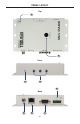
PANEL LAYOUT Top 1 2 Front 3 4 8 Back 5 6 7 4
PANEL DESCRIPTIONS 1 Power This LED will indicate the current power state. The LED is green when the unit is powered ON. 2 IR Sensor The IR receiver is provided for the Mini PACS to learn new IR commands. Use the Web Interface or Telnet for this procedure. See pages 17 - 29 for more information. 3 IP Reset This button is placed beneath the enclosure surface to prevent an accidental reset.
CONNECTING THE MINI PACS How to Connect the Mini PACS 1. Connect the included RS-232 cable between the Mini PACS and the RS-232 device. 2. Connect up to three (3) single or dual IR Emitters to the Mini PACS. Make sure that each LED emitter is close to the IR sensor of the A/V devices to be controlled. 3. Connect the relay leads from the control motors of projection screens, blinds, or draperies to the relay outputs on the back panel of the Mini PACS. 4.
CONFIGURING THE IP ADDRESS Setting the IP Address The Mini PACS is designed to control devices over a network using a built-in Web server or via Telnet. Before using Telnet control or the built-in Web Server, the network settings for the Mini PACS must be configured via IP. Before connecting the Mini PACS to a network, locate the label on the bottom of the Mini PACS. The MAC address and the default IP address will be listed on the label.
CONFIGURING THE IP ADDRESS If you computer has an IP address of 192.168.1.(x), and 192.168.1.72 is an available address, you can access the Mini PACS by entering 192.168.1.72 in your Web browser. Otherwise use the following procedure to change the Mini PACS IP address to match your network: 1. Access the Network Setting control panel in Windows and locate your LAN connection. Under Windows 7®, this can be done by clicking Start > Control Panel > Network Sharing Center > Change Adapter Settings. 2.
CONFIGURING THE IP ADDRESS 3. Click on the Properties button to display the Local Area Connection Properties dialog. 4. Click on Internet Protocol Version 4 (TCP/IPv4). Internet Protocol Version 4 (TCP/IPv4) Click to highlight this Network protocol. 5. Click the Properties button to display the Internet Protocol Version 4 (TCP/ IPv4) Properties dialog.
CONFIGURING THE IP ADDRESS STOP: Write down the current IP settings before making changes, since you will need to restore the old settings later. If the Properties are set to “Obtain an IP address automatically” and “Obtain DNS server address automatically”, you do not need the actual address settings. 6. Change the IP settings to the following: Subnet mask 255.255.255.0 Use the following IP address Click this radio button. IP address 192.168.1.
CONFIGURING THE IP ADDRESS 7. Click the OK button, then close all Control Panel windows. 8. Refresh your Web browser and go to http://192.168.1.72 to open the Mini PACS Web Server. 9. Go to the Configuration Menu (see page 33) and change the Mini PACS IP address to an appropriate address for your network. 10. Click ”Save Changes”, “Reboot”, and “OK” to save the new IP address. 11.
WEB INTERFACE The Built-in Web Server The Mini PACS includes a built-in Web server which provides an intuitive Web interface. If TCP/IP is not configured on the Mini PACS, then see page 7 for details on configuring the Mini PACS. If the Mini PACS is already configured for use on a network, then open a Web browser and type in the IP address of the Mini PACS. The built-in Web server provides control over RS-232, IR emitters, relays, and general configuration.
WEB INTERFACE RS-232 Menu The RS-232 Menu allows you to change the RS-232 port settings on the Mini PACS. Description Provide a name to the device connected to this port (e.g. “SonyTV”, “Samsung”, etc.
WEB INTERFACE RS-232 Settings Some RS-232 settings use a drop-down menu for selecting different options. For example, to select the Baud Rate, click the arrow icon then click on the required port speed: Arrow Icon Indicates a dropdown list. Click to list the available baud rates. Baud Rate Sets the baud rate for the port. Range: [100 bps - 115200 bps] Parity Sets the parity bit. Options: Even, Odd, None, Mark, Space Stop Bits Sets the stop bit.
WEB INTERFACE TCP / UDP Bridging Settings UDP Protocol is used by some control systems, including Gefen’s GAVA system, for faster response. When using UDP you can broadcast the message by using the IP address: 255.255.255.255. Use TCP unless otherwise instructed by your Control System User Manual, or by Gefen Technical Support. See page 56 for a full explanation of these settings.
WEB INTERFACE TCP / UDP Bridging Settings Start Delimiter Value Range: 00 - FF (“wildcard” characters are acceptable, e.g. **) The Start Delimiter can be up to three ASCII characters (3 bytes), in hex format. For example, 0D0A is CR + LF (Carriage Return + Line Feed). The delimiters are used by some control systems to filter incoming data. Contact Gefen Technical Support for details if you need to use them.
WEB INTERFACE IR Emitters Menu The Mini PACS has three (3) IR Emitter (IR back-channel) ports. The Mini PACS can use any one of these IR Emitter ports to send IR commands to the source device. Up to 64 IR commands can be stored per device. IR configuration files can be saved, downloaded, uploaded, edited, and deleted. Select Outputs To Test Commands List of IR Emitter output p p ports used to test the IR commands. Select Device List of devices which have been stored in the PACS.
WEB INTERFACE Command Name Used to enter / edit the name of each IR command. This is a required field. Up to sixty-four (64) IR commands can be stored per device. Each Command Name can be up to 20 Alphanumeric characters or spaces. Advanced View Click this link to toggle between Basic View and Advanced View. 18 Test Press the Test button to validate the learned IR command. One or more outputs must be selected and an IR Emitter plugged in before test can be sent.
WEB INTERFACE Learn All Performs a “stepthrough” when learning IR commands from a template (see page 26). Advanced View Click the Advanced View link to display additional options for learning or deleting IR commands. Learn Click the Learn button to learn a new IR command (see page 22). Delete Click the Delete button to delete a learned IR command. Deleted commands will be permanently removed after saving changes.
WEB INTERFACE Model No. (optional) This is the device model number (e.g. KDL40EX729, etc.) This field is used by the GAVA to sort the IR library. Max. Length: 10 characters (no dashes, slashes, etc). Manufacturer (optional) This is the device manufacturer’s name (e.g. Sony, Yamaha, etc). This field is used by the GAVA to sort to the IR library. Max. Length: 10 characters Class (optional) This is the generic class of the device: Display, Disc, AVR (A/V Receiver), or STB (Set-Top Box).
WEB INTERFACE Bro owse... Click this button to open a list of files on your computer to Upload. It will open the last selected folder on your computer with a default selection of All Files (*.*). Download IR File to PC Press this button to save the currently-displayed Device IR commands to an XML file on your computer. Choose a folder location and filename that will allow you to easily locate the file at a later time. Save Changes Press this button to save any changes to the currently-displayed Device.
WEB INTERFACE Adding a new IR Device The Mini PACS can hold up to 20 IR devices in memory. Each device may have up to 64 Commands. If you are building a library, you may need to delete some devices from the Mini PACS once they are learned and saved, to make room for more devices. However, if you have several of the same devices with separate IR emitters, you can use the same IR “Device Name” for all of them, but specify a different output for each one when you send the commands.
WEB INTERFACE 10. Find the IR remote for the new device. Make sure the batteries are fresh! Hold the remote so it is pointing at the IR window on the Mini PACS, and is about 6” away from the window. 11. Click the “Learn” button for the first named Command. 12. You will be prompted to press the remote button that matches the Command Name you are learning. Press the button firmly- do not hold it down, or just hit it quickly.
WEB INTERFACE 14. If the commands match, the Mini PACS will return to the main screen, and the new command will now be green. 15. If a code is learned incorrectly, you may overwrite it by repeating steps 11 13. The Mini PACS will warn you that the command is already in memory, and ask you to confirm that you want to overwrite the existing code. Press “OK” to do so. Once a Command is learned, its Command Name may not be changed.
WEB INTERFACE Bedroom_DVD Disc Sony BDPS580 power_toggle 1175 64 564 149 279 ... 149 137 5149 0 1 power_off 1200 64 564 148 280 ... 136 5007 0 1 volume_up 1200 64 564 148 137 ...
WEB INTERFACE Adding a new IR device from a Template Templates are useful when you want to ensure that similar commands for different product models have identical Command Names. This will simplify the process of programming your control system, and allow you to replace one disc player, for example, with another model, without having to change the control system programming.
WEB INTERFACE 6. Since this is a template file, the Command Names will be yellow, rather than green. This means that only the names, and not the IR data, have been stored. 7. Click on the “Advanced View” button above the Command Name list. This adds the “Learn” and “Delete” buttons for each Command, and a button named “Learn ALL” above. 8. Find the IR remote for the new device.
WEB INTERFACE 12. If the commands match, the Mini PACS will prompt you for the next Command in the list. 13. If you are prompted for a command that does not exist on your remote, you can press the “SKIP Command” button, and you will be prompted for the next button on the list, or you can press “EXIT IR Learning” to end the process. If you start the Learn ALL process again, it will start with the first un-learned command, and skip any commands that have previously been learned.
WEB INTERFACE 18. You can delete any commands that are not available for that specific remote by clicking the “Delete” button for those commands. Deleted buttons will be removed when changes are saved. Un-learned template commands will be saved for later learning. 19. Press “Save Changes” to save the learned Commands to the Mini PACS.
WEB INTERFACE Relays Menu The Mini PACS provides two Normally-Open (NO) relays which can be used for controlling lighting systems, curtains, motorized screens, or various other automation devices. Each relay contact is rated for 1A at 30V DC. +12V DC and Ground are also provided for convenience. Relay Buttons Click one of these buttons to name and configure a relay. When a relay has been associated to a specific event, the event will appear under Devices.
WEB INTERFACE Save Changes Saves the trigger event. Delete Deletes the trigger name and resets settings to default. Pulse Duration (ms) Required when Type is set to Pulse. Range: 0 -10000. (1000 = 1 sec.) Default State Sets the default state of the trigger. Options: Open, Close. Device Name Enter the name of the device associated with this trigger. 31 Type Sets the type of relay trigger. If set to Pulse, the Pulse Duration (ms) must be specified. Level stays at the new state until changed.
WEB INTERFACE Testing Relays Press the “Set Closed” or “Set Open” buttons to manually change the state of a relay. If the “Type” is set to “Pulse”, the relay will revert to its default state after the Pulse Duration period has expired. Relay ID Relay 1 and Relay 2 Relay State Indicates the current state of the relay. If the relay is open, then Open is displayed in red. If the relay is closed, then Closed displayed in green. Press the Set Close or Set Open button to change the current state of a relay.
WEB INTERFACE Configuration Menu The Configuration Menu allows management of TCP/IP configuration, login credentials, firmware upgrades, and system resets. IP Configuration IP Address Sets the IP address. This must be a valid and unused address on your local network. Maximum value for each number is 255. MAC Address The MAC address cannot be changed. NOTE: The top row (Current) indicates the current settings. The second row (Default) indicates the default settings. The default settings cannot be changed.
WEB INTERFACE Subnet Sets the subnet mask. The default settings is 255.255.255.0 Gateway Sets the IP address of your router (IP gateway). Maximum value for each number is 255. Web UI Port Sets the HTTP listening port. The default setting is 80. Refresh Refreshes the IP configuration to obtain the latest changes. Telnet Port Sets the Telnet listening port. The default port setting is 23. Factory Default Sets the IP Configuration settings to factory (default) settings.
WEB INTERFACE Telnet Login Settings Force Password on Connect Forces password prompt when connecting via Telnet. Display Welcome Message on Connect Displays a “Welcome to PACS Telnet Server” message when Telnet connection opens. Save Changes Saves the current changes to the Telnet Login Settings. Password Sets the password. Maximum password length is 20 characters. The password is case-sensitive. UserName Sets the user name. Maximum user name length is 20 characters. The user name is case-sensitive.
WEB INTERFACE Firmware Update Get Firmware Checks the Gefen Web site for the latest firmware. The current version of firmware is displayed above this button. Browse... Click the Browse... button to select the firmware file after it has been downloaded. Update Click the Update button after the firmware file has been selected using the Browse... button. Reboot Reboot the PACS after making any configuration changes.
WEB INTERFACE System Reset Yes To All Check this box to perform a System-Wide Reset during a reset procedure. Set Triggers To default Place a check mark in this box to set triggers to default settings when resetting the PACS. ATTENTION: A System-Wide Reset will delete alll Commands and Device data, reset the IP address, and reset the PACS to factory (default) settings. WARNING: Your IP connection will be dropped if you change the IP address.
WEB INTERFACE Delete IR Commands Place a check mark in the box to delete all learned IR commands during a reset. Delete IR Devices & Commands Place a check mark in the box to delete all IR devices and learned IR commands during a reset. Delete IR Commands Place a check mark in the box to set the serial ports to their default settings.
WEB INTERFACE System Settings The System Settings section allows you to upload or restore a file containing all of the IP settings, RS-232 settings, trigger settings, and all IR files, devices, and commands. The default name of this XML file is “Settings_xml.gfn”. This file may be copied to another Mini PACS, which will then be an exact duplicate of the source Mini PACS (please note that you will have to change the IP address of the duplicate Mini PACS if both units will be connected to the same network).
WEB INTERFACE It is important to understand that this XML file does not actually exist in the Mini PACS. Rather, it is created “on-the-fly” by the Web GUI when it is downloaded. When a new settings file is presented for an update, it is parsed by the Mini PACS firmware, and the data is stored in the appropriate locations in the Mini PACS memory.
IP (TELNET) CONTROL SETUP The Mini PACS may be manually operated using the Web server Graphical User Interface (GUI), or by an automation system (such as the Gefen GAVA System) that is capable of sending Telnet serial commands to the Mini PACS via IP. The Web interface allows setting RS-232 communications parameters. RS-232 device commands are not stored in the Mini PACS, and cannot be sent through the Web interface.
IP (TELNET) CONTROL SETUP 3. Click “Save Settings”. 4. Open HyperTerminal or another Terminal Emulation program on your computer. 5. Open a new session with a Host Address that matches the IP address of the Mini PACS, and set the Port Number to 49202. 6. Type “help ?” in the terminal window, and a list of commands from the AUDDEC-N should scroll in the window, indicating successful communication with the AUDDEC-N.
RS-232 / TELNET COMMANDS IP Configuration Command Description #change_relay_state Changes the current relay state #display_telnet_welcome Set Telnet welcome message on login #load_relay_params Loads relay parameters from memory #save_relay_params Saves relay parameters to memory #set_http_port Sets the Web server listening port #set_pass Prompts for password when using Telnet #set_relay_params Sets the relay parameters #set_serial_mode Sets the specified serial port mode #set_serial_params
RS-232 / TELNET COMMANDS #change_relay_state Command The #change_relay_state command changes the state of a relay. Specify the relay number and then the initial state (open or closed) of the relay. Syntax y : #change_relay_state param1 param2 Parameters: param1 Relay [1 - 2] param2 State [0 - 1] State Meaning 0 Open 1 Closed #display_telnet_welcome Command The #display_telnet_welcome sets (enables/disables) the Telnet welcome message on login.
RS-232 / TELNET COMMANDS #load_relay_params Command The #load_relay_params command loads relay settings from memory. Syntax y : #load_relay_params Parameters: None #save_relay_params Command The #save_relay_params command saves relay settings to memory. Syntax y : #save_relay_params Parameters: None #set_http_port Command The #set_http_port command sets the Web server listening port.
RS-232 / TELNET COMMANDS #set_pass Command The #set_pass command sets Telnet password. The maximum length of the param1 is 20 characters. The password is case-sensitive. Syntax y : #set_pass param1 Parameters: param1 Password Default: Admin #set_relay_params Command The #set_relay_params command sets the input trigger parameters.
RS-232 / TELNET COMMANDS #set_serial_mode Command The #set_serial_mode command sets the serial port mode. Syntax y : #set_serial_mode param1 Parameters: param1 Mode [1 - 3] Mode Meaning 1 Terminal 2 TCP Bridge 3 UDP Bridge Example: p #set_serial_mode 1 Default: Default is “TCP Bridge” mode.
RS-232 / TELNET COMMANDS #set_serial_params Command The #set_serial_params command sets the serial port parameters.
RS-232 / TELNET COMMANDS #set_telnet_port Command The #set_telnet_port command sets the Telnet listening port. The default port value is 23. Syntax y : #set_telnet_port param1 Parameters: param1 Port [0 - 65535] #set_user_name Command The #set_user_name command sets the Telnet user name. The maximum length of param1 is 20 characters. The user name is case-sensitive.
RS-232 / TELNET COMMANDS #sgateway Command The #sgateway sets the IP gateway (router) address. Dot-decimal notation must be used when specifying the IP address. Syntax y : #sgateway param1 Parameters: param1 IP gateway Example: p #sgateway 192.168.1.1 Default: 192.168.1.254 #show_pass Command The #show_pass command shows the Telnet password for login (if required). Syntax y : #show_pass Default: Admin #set_telnet_port Command The #set_telnet_port command sets the Telnet listening port.
RS-232 / TELNET COMMANDS #show_relay_params Command The #show_relay_params command displays the current relay parameters. param1 specifies the relay channel (1 - 10) to query. Set param1 to 0 to display the parameters for each of the 10 channels.
RS-232 / TELNET COMMANDS #show_serial_params Command The #show_serial_params command displays the serial port parameters. Syntax y : #show_serial_params Parameters: None Example: p #show_serial_params Serial Port 1 parameters: Word length = 8 bits Stop bits = 1 bit Parity = No Baud rate = 19200 Bps Line delay = 0 ms #show_user_name Command The #show_user_name command returns the user name required for login.
RS-232 / TELNET COMMANDS #sipadd Command The #sipadd command sets the IP address for the Mini PACS. Dot-decimal notation must be used when specifying the IP address. The default IP address is 192.168.1.72. The Mini PACS must be rebooted to change the IP address. WARNING: Your IP connection will be dropped if you change the IP address. You must reset your computer to communicate with the new IP address and then reopen your Web browser and go to the new address.
RS-232 / TELNET COMMANDS #system_wide_reset Command The #system_wide_reset command performs a system-wide reset. Each parameter specifies the hardware to reset.
RS-232 / TELNET COMMANDS #use_telnet_pass Command The #use_telnet_pass command requires or disables login credentials.
RS-232 / TELNET COMMANDS Bridging Settings RS-232 Feedback and Delimiters One advantage of RS-232 serial control over IR control is that RS-232 offers 2-way communications between a device and the control system. This allows the controlled device to provide feedback to confirm that its operating state matches the control system’s assumptions.
RS-232 / TELNET COMMANDS Command Description #set_addel Sets add delimiter mode #set_end_del Sets end-delimiter mode and value #set_send_byte_cnt Sets the end-delimiter mode and value #set_send_time_out Sets the time-out value for sending data collected from a device #set_start_del Sets start-delimiter mode and value #set_tcp_br_port Sets the TCP Bridge server listening port #set_udp_br_port Sets the UDP port #set_udp_remote_br Sets UDP bridge parameters #set_adddel Command The #set_adddel
RS-232 / TELNET COMMANDS #set_end_del Command The #set_end_del command sets the end-delimiter mode and value. Syntax y : #set_end_del param1 param2 Parameters: param1 On / Off [0 - 1] param2 Delimiter value [00 - FF] Example: p #set_end_del 1 B0 Notes: If param2 is set to 0, then the start delimiter is turned “off”. param2 2 is used to “enable” or “disable” the delimiter value. #set_send_byte_cnt Command The #set_send_byte_cnt command sets the end-delimiter mode and value.
RS-232 / TELNET COMMANDS #set_send_time_out Command The #set_send_time_out command sets the timeout value for sending data collected from a device to the control system in Bridging Mode when a Start Delimiter and End Delimiter have been set. If no data has been collected for the specified time, the data is sent without waiting for the End Delimiter.
RS-232 / TELNET COMMANDS #set_start_del Command The #set_start_del command sets the start-delimiter mode and value. Syntax y : #set_start_del param1 param2 Parameters: param1 param2 State [0 - 1] Value Meaning 0 Off 1 On Delimiter value [00 - FF] Examples: p #set_start_del 1 A0 #set_start_del 0 Notes: If param1 is set to 0, then the start delimiter is turned “off”. In that case, param2 is optional and is ignored by the Mini PACS. param1 is used to “enable” or “disable” the delimiter value.
RS-232 / TELNET COMMANDS #set_tcp_br_port Command The #set_tcp_br_port command sets the TCP Bridge server listening port. Syntax y : #set_tcp_br_port param1 Parameters: param1 Port Number Example: p #set_tcp_br_port 49202 TCP Bridge port set to: 49202 Default: TCP Bridge to Serial Port: 49202 Notes: Do not change the TCP Bridge server port values unless instructed by Gefen Technical Support.
RS-232 / TELNET COMMANDS #set_udp_br_port Command The #set_udp_br_port command sets the UDP server listening port. Syntax y : #set_udp_br_port param1 Parameters: param1 Port number [0 - 65535] Example: p #set_udp_br_port 50202 UDP Bridge port set to: 50202 Default: UDP Bridge to Serial Port: 50202 #set_udp_remote_br Command The #set_udp_remote_br command sets the UDP bridge parameters.
RS-232 / TELNET COMMANDS IR Device Setup Command Description #add_class Specifies the Class of the device #add_device Adds a new device #add_manufacturer Specifies the Manufacturer for the device #add_mod_num Specifies the Model Number for the device #delete_device Deletes a device from the Mini PACS #delete_ir_cmd Deletes a device by removing it from the IR list #learn_ir_cmd Initializes the learning of a new IR command #play_ir_cmd Plays an IR command stored in memory #show_device_tags
RS-232 / TELNET COMMANDS #add_device Command (required) The #add_device command adds a new device. The ADD_DEVICE command must be excuted before learning a new device. The Device Name must be alphanumeric characters and spaces, and is limited to 20 characters in length. (Note that spaces will be replaced with underscores (_) in the XML files).
RS-232 / TELNET COMMANDS #add_mod_num Command (optional) The #add_mod_num command adds or updates the “Model No.” tag for the specified device. The “Model No.” tag is used by GAVA to identify devices, and along with the “Manufacturer” tags, may be helpful for users to identify their IR library files.
RS-232 / TELNET COMMANDS #delete_ir_cmd Command The #delete_ir_cmd command deletes the IR command from the specified device.
RS-232 / TELNET COMMANDS #learn_ir_cmd Command The #learn_ir_cmd command initializes the learning of a new IR command.
RS-232 / TELNET COMMANDS #play_ir_cmd Command The #play_ir_cmd command plays an IR command stored in memory. Syntax y : #play_ir_cmd param1 param2 param3 Parameters: param1 Command Name param2 Device Name param3 Emitter Port [1 - 3] Notes: Emitter Port 0 is all Ports. Multiple Emitter Port Numbers may be entered. Example: p #play_ir_cmd play TV 1 2 Playback IR Command: pwr for Device: TV End of emitter output signal IMPORTANT: Device Names and Command Names are all casesensitive.
RS-232 / TELNET COMMANDS #show_device_tags Command The #show_device_tags command shows the existing tags (Class, Manufacturer and Model Number) for a specified Device. The Device Name is actually used by Mini PACS to send an IR command. The additional tags are not required by Mini PACS, but are used by GAVA, and may be helpful for users to keep their IR files organized. For example, it may be convenient to call a device, “Bedroom_Blu_Ray” for programming purposes.
RS-232 / TELNET COMMANDS #show_devices Command The #show_devices command displays all devices in the IR list.
RS-232 / TELNET COMMANDS #show_ir_cmds Command The #show_ir_cmds command displays all IR commands for a stored device.
RS-232 / TELNET COMMANDS #show_ir_data Command The #show_ir_data command displays raw data from the memory. Syntax y : #show_ir_cmd param1 param2 Parameters: param1 Command Name param2 2 Device Name Example: p #show_ir_data pwr tv Command: pwr for Device: tv Carrier frequency = 40.
RS-232 / TELNET COMMANDS For remotes with toggle bits there will be additional data: Command: 9 for Device: tv Carrier frequency = 40.
RS-232 / TELNET COMMANDS General Query Command Description #help Displays a complete list of commands #ipconfig Displays all TCP/IP settings #show_ver_data Displays the Mini PACS version information #help Command The #help command displays help on the specified command. If param1 is not included, then the full list of commands is displayed. Syntax y : #help [param1] Parameters: param1 Command [optional] Example: p #help #show_serial_params Cmd #show_serial_params: Show Serial Port parameters: e.
RS-232 / TELNET COMMANDS #ipconfig Command The #ipconfig displays all TCP/IP settings. Syntax y : #ipconfig Parameters: None Example: p #ipconfig ------------- Mini PACS TCP/IP settings ------------MAC addr = 00:1C:91:02:90:01 IP addr = 192.168.1.72 Net Mask = 255.255.255.0 Gateway = 192.168.1.
RS-232 / TELNET COMMANDS #show_ver_data Command The #show_ver_data command displays the Mini PACS version information. Syntax y : #show_ver_data Parameters: None Example: p #show_ver_data Hardware version 0 Firmware version 1.
APPENDIX Controlling the Mini PACS via RS-232 The Mini PACS is generally intended to be controlled via IP, in order to control RS-232, IR, and trigger-operated devices that are connected to it. Under some circumstances, it may be useful to control the Mini PACS via an RS-232 port, such as to use the Mini PACS as an RS-232-to-IR or RS-232-to-trigger converter or if it is more convenient to use an RS-232 connection than an IP connection for configuration.
APPENDIX Learning IR Commands via Telnet The Mini PACS has eight (3) IR Emitter outputs. Each of these IR Emitters can be connected to device. The Mini PACS can learn new IR commands and then send the learned IR command to any or all of the devices at once. The Mini PACS can store commands for up to 20 devices. Each of the stored devices can have up to 64 commands. In the example below, we will have the Mini PACS learn a play command for a Sony DVD player. 1. Access the Mini PACS using Telnet.
APPENDIX NOTE: If the Mini PACS is unable to validate the IR command, the Mini PACS will prompt you to repeat steps 4 and 5. If the IR command data is valid, then the IR command will be saved to memory. The Mini PACS will ignore IR data that cannot be validated. 6. If the Mini PACS verifies that the data is the same, then it is saved: Data compare ok, checking for available space in FLASH New command saved in FLASH! 7.
SPECIFICATIONS Relays........................................ (2) NO relay contacts with +12V DC and Ground Relay Connections............................................. 6-position Phoenix terminal block Relay Contact Rating........................................................................ 1A @ 30V DC Ethernet Port............................................................................. (1) RJ-45, shielded RS-232 serial ports........................................................................
WARRANTY Gefen warrants the equipment it manufactures to be free from defects in material and workmanship. If equipment fails because of such defects and Gefen is notified within two (2) years from the date of shipment, Gefen will, at its option, repair or replace the equipment, provided that the equipment has not been subjected to mechanical, electrical, or other abuse or modifications.
Rev A2 1.11 20600 Nordhoff St., Chatsworth CA 91311 1-800-545-6900 818-772-9100 www.gefentoolbox.com Pb This product uses UL or CE listed power supplies. fax: 818-772-9120 support@gefentoolbox.