
User's Manual
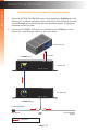
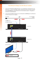
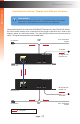
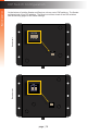
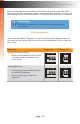
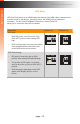


Table Of Contents
page | 14
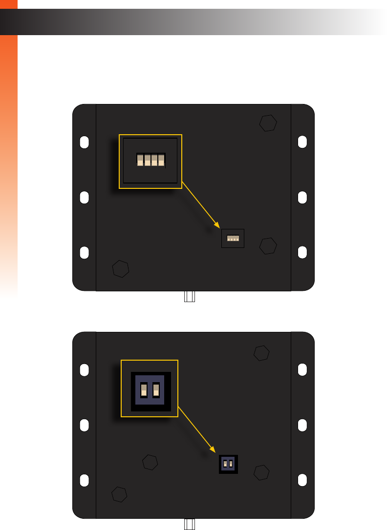
DIP Switch Conguration
On the bottom of both the Sender and Receiver unit are a set of DIP switches. The Sender
unit has a bank of four DIP switches. The Receiver unit has a bank of two DIP switches.
See the following pages for DIP switch settings.
ON RSN
1 2 3 4
Power
Link
24V DC
HDMI In
Link
IR In/Ext
IR Out
GTB-UHD-HBTL-S
Sender unit
Power
Link
24V DC
HDMI Out
Link
IR In/Ext
IR Out
GTB-UHD-HBTL-R
ON
1 2
Receiver unit
Basic Operation
Basic Operation
ON RSN
1 2 3 4
Power
Link
24V DC
HDMI In
Link
IR In/Ext
IR Out
GTB-UHD-HBTL-S
Power
Link
24V DC
HDMI Out
Link
IR In/Ext
IR Out
GTB-UHD-HBTL-R
ON
1 2