Home Theater Audio Processor GTV-HT-AUDPROC User Manual www.gefentv.
ASKING FOR ASSISTANCE Technical Support: Telephone (818) 772-9100 (800) 545-6900 Fax (818) 772-9120 Technical Support Hours: 8:00 AM to 5:00 PM PST Monday thru Friday. Write To: Gefen, LLC c/o Customer Service 20600 Nordhoff St Chatsworth, CA 91311 www.gefentv.com support@gefentv.com Notice Gefen, LLC reserves the right to make changes in the hardware, packaging, and any accompanying documentation without prior written notice.
CONTENTS 1 Introduction 2 Operation Notes 3 Features 4 Panel Layout 5 Panel Descriptions 8 Connecting The Home Theater Audio Processor 9 GTV-AUD-IR Remote Layout 10 GTV-AUD-IR Remote Descriptions 11 GTV-AUD-IR Remote Installation 11 Home Theater Audio Processor Remote Installation 12 Operating the Home Theater Audio Processor 20 Speaker Format Table 22 Bi-Amping 23 RS-232 Serial Control Interface 24 RS-232 Commands 26 Specifications 27 Warranty
INTRODUCTION Congratulations on your purchase of the GefenTV Home Theater Audio Processor. Your complete satisfaction is very important to us. GefenTV GefenTV is a unique product line catering to the growing needs for innovative home theater solutions. Gefen specializes in total integration for home theater connectivity, while also focusing on going above and beyond customer expectations to ensure you get the most from your hardware.
OPERATION NOTES READ THESE NOTES BEFORE INSTALLING OR OPERATING THE HOME THEATER AUDIO PROCESSOR • The GefenTV Home Theater Audio Processor is designed to be used with speakers, using five full-bandwidth channels and one low frequency channel. RCA outputs are provided for connecting the GefenTV Home Theater Audio Processor to a separate audio amplifier. Two (2) additional connectors, both speaker and RCA, are available for bi-amping the front-left and front-right channels (see page 22 for details).
FEATURES Supported HDMI 1.3 Features • 225 MHz (up to 12-bit YUV 4:4:4 @ 1080p) • Deep Color support (x.v.Color) • Lip-Sync pass-through • CEC pass-through Features • Separates digital audio from the HDMI or of S/PDIF inputs and decodes up to 5.
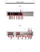
PANEL LAYOUT Front 1 2 3 4 5 6 7 8 9 10 11 Back 22 21 20 17 12 13 14 4 15 16 19 18
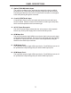
PANEL DESCRIPTIONS 1 Power Status LED Indicator This LED will indicate the current power state. When the LED is red, the unit is in standby mode. When the LED is green, the unit is on. 2 Infrared Sensor This infrared sensor will accept commands from the included GTV-AUD-IR remote control. This sensor requires line-of-sight between the unit and remote for proper operation. 3 Mute / Right Button This button will cycle between Mute-On and Mute-Off modes when not in the Menu System.
PANEL DESCRIPTIONS 9 Mode / OK Button This button will change the Processing Mode when not in the Menu System. While in the Menu System this will be used as a confirmation button. 10 Exit Button This button is used to exit the current menu level and return to the previous/ parent level. This button will exit the entire Menu System when on the top most level. 11 Power Button This button will toggle between the ON and STANDBY power states. An LED status indicator will signify the current power state.
PANEL DESCRIPTIONS 17 Optical (TOSLINK) Audio Output This output is constantly active. Audio that is extracted from the input HDMI source device or via the coaxial input is directly output through this connector. Processing and features of the Home Theater Audio Processor are not applied to the audio passing through this connector. 18 Coaxial (S/PDIF) Audio Input A coaxial audio source can be connected and used as the main audio input source if desired.
CONNECTING THE HOME THEATER AUDIO PROCESSOR How to Connect the Home Theater Audio Processor 1. Connect an HDMI source device to the HDMI input port of the Home Theater Audio Processor using the included HDMI cable. 2. Optionally, connect an additional audio source to the coaxial (S/PDIF) input using a user supplied coaxial cable. 3. Connect up to 6 speakers to the speaker terminals on the back panel of the Home Theater Audio Processor. The following connection terminals are available: • • • • • • • 4.
GTV-AUD-IR REMOTE LAYOUT Home Theatre Audio Processor Remote Control 1 15 2 14 13 12 3 11 10 4 9 5 8 6 7 9
GTV-AUD-IR REMOTE DESCRIPTIONS 1 Power Off This is a discrete power off button. Pressing this button will turn the Home Theater Audio Processor off. 2 Mode This button functions the same as the Mode button on the front panel. 3 Left This button will navigate left when using the Menu System. 4 Exit This button functions the same as the Exit button on the front panel. 5 Mute This button cycle between mute on and mute off modes. When mute is applied there will not be any audio output.
GTV-AUD-IR REMOTE INSTALLATION To use the GTV-AUD-IR remote, remove the battery cover on the back of the remote to reveal the battery compartment. Insert the included battery into the open battery slot. The positive (+) side should be facing up. Ensure that both DIP (Dual Inline Package) switches are in the OFF position. Replace the battery cover. The remote ships with 2 batteries. One battery is needed for operation and the other battery is complimentary.
OPERATING THE HOME THEATER AUDIO PROCESSOR NAVIGATION The Home Theater Audio Processor uses a series of buttons, located on the front panel, for all input selection and feature functions. All status information, such as the input audio type, are always available on the front panel LCD Screen. User adjustable features, such as speaker distance and processing modes, can be navigated and adjusted by referencing the LCD Screen.
OPERATING THE HOME THEATER AUDIO PROCESSOR MAIN DISPLAY The Main Screen will display useful information to the user. It displays the currently selected input port and audio input format. The currently used output format can also be displayed by pressing the ▼ button. Pressing the ◄ or ► buttons while on this screen will have no effect. Please see below for the Main Screen layout. 1 2 3 4 1 This section will display the currently selected audio input source.
OPERATING THE HOME THEATER AUDIO PROCESSOR 3 - AUDIO FORMAT This portion of the screen will display the current audio inputs format. Please use the table below to determine what formats are accepted by each input type. Input Supported Audio Formats LPCM Supported Channels 6 HDMI Dolby Digital 6 Dolby Pro Logic II 6 LPCM 2 Dolby Digital 6 Dolby Pro Logic II 6 Coaxial 4 - PROCESSING MODE This portion of the screen will display the currently used processing mode.
OPERATING THE HOME THEATER AUDIO PROCESSOR MENU SYSTEM NAVIGATION The Menu System will allow the user to configure features of the Home Theater Audio Processor. The front panel buttons are used to navigate the Menu System. Feature configuration can also be accomplished via the IR remote control. To enter the Menu System, press the MENU button located on the front panel. The Main Menu will become available, The following menu options are available: • Speaker Size This option will set the speaker size.
OPERATING THE HOME THEATER AUDIO PROCESSOR SPEAKER SIZE This menu option will allow the user to select the speaker size to either SMALL or LARGE. When a speaker size is set to SMALL, all frequencies below 80Hz are automatically routed to the subwoofer channel. When a speaker size is set to LARGE, all frequencies will be routed to the speaker. All speakers except the front left and right channels have an option to disable the use of that channel.
OPERATING THE HOME THEATER AUDIO PROCESSOR • Front R - These settings will affect the front right channel output (default is +00dB). • Surr R - These settings will affect the surround right channel output (default is +00dB). • Surr L - These settings will affect the surround left channel output (default is +00dB). • Sub - These settings will affect the subwoofer channel output (default is +00dB). Use the ◄ and ► buttons on the front panel to change options for the selected speaker.
OPERATING THE HOME THEATER AUDIO PROCESSOR TONE CONTROL This menu option will allow the user to adjust the bass and treble settings. These features were designed to allow the user to adjust the sound to their taste. Both the treble and bass settings can be adjusted in 1db increments between -12dB and +12dB . Use the ▼ and ▲ buttons on the front panel to select either the treble or bass option (default for both options are +00dB).
OPERATING THE HOME THEATER AUDIO PROCESSOR When finished, press the ▼ or ▲ to move to another selection. Alternately, the user can press the OK button to immediately cycle to the next option. To return to the previous menu, press the EXIT button. To exit the entire Menu System, press the MENU button. MISCELLANEOUS SETUP This menu option will allow the user to set miscellaneous settings. The following options are in the menu: • DIST.
SPEAKER FORMAT TABLE SPEAKER AND FORMAT TABLE Speaker Size FL_R PCM2ch / Dolby_2ch PCM2ch / Dolby_2ch Small FavProcMode CT SL_R SUB SL_R PLII(1) Direct(2) Stereo(3) Mch Stereo(4) Mono(5) Small Small onsub Small 5.1ch 2.1ch 2.1ch 5.1ch 1.1ch Small Large onsub Large 5.1ch 2.1ch 2.1ch 5.1ch 1.1ch Large Small onsub Small 5.1ch 2.1ch 2.1ch 5.1ch 1.1ch Large Large onsub Large 5.1ch 2.1ch 2.1ch 5.1ch 1.1ch off Small onsub Small 4.1ch 2.1ch 2.1ch 4.1ch 2.
SPEAKER FORMAT TABLE SPEAKER AND FORMAT TABLE Speaker Size FL_R PCM5.1ch / AC3_5.1ch PCM5.1ch / AC3_5.1ch Small FavProcMode CT SL_R SUB SL_R PLII(1) Direct(2) Stereo(3) Mch Stereo(4) Mono(5) Small Small onsub Small — 5.1ch 2.1ch 5.1ch 1.1ch Small Large onsub Large — 5.1ch 2.1ch 5.1ch 1.1ch Large Small onsub Small — 5.1ch 2.1ch 5.1ch 1.1ch Large Large onsub Large — 5.1ch 2.1ch 5.1ch 1.1ch off Small onsub Small — 4.1ch 2.1ch 4.1ch 2.
BI-AMPING BI-AMPING The Home Theater Audio Processor features 2 additional outputs, both speaker terminals and RCA outputs, for bi-amping the front right and left audio channels. These outputs were intended to supply an additional set of front right and left audio channels for use with an amplifier or bi-ampable speaker. Please refer to your amplifier and speaker manual for proper bi-amping connection procedures.
RS-232 SERIAL CONTROL INTERFACE 54321 12345 9876 6789 Only Pins 2 (RX), 3 (TX), and 5 (Ground) are used on the RS-232 serial interface RS-232 Settings Bits per second ................................................................................................. 19200 Data bits .................................................................................................................... 8 Parity ...................................................................................................
RS-232 COMMANDS RS-232 Command Table Command Code Response Description POWER 0 > POWER OFF POWER OFF POWER 1 > POWER ON POWER ON VOL +10~-60 > VOL +10~-60 Audio volume adjust from maximum to minimum VOL + > VOL +10~-60 Increase audio by 1 VOL - > VOL +10~-60 Decrease audio by 1 MODE 0 > PL II Audio FAV PROC setup to Dolby Pro Logic II mode MODE 1 > DIRECT Audio FAV PROC setup to DIRECT mode [Default:DIRECT] MODE 2 > STEREO Audio FAV PROC setup to STEREO mode MODE 3 > MCH Audio
RS-232 COMMANDS Command Code Response Description SIZEFLR 0 OK Front speaker Small SIZEFLR 0 OK Front speaker Large SIZEC 0 OK Center speaker Small SIZEC 1 OK Center speaker Large SIZEC 2 OK Center speaker Off SIZELR 0 OK Surround speaker Small SIZELR 1 OK Surround speaker Large SIZELR 2 OK Surround speaker Off SUB 0 OK Subwoofer Off SUB 1 OK Subwoofer On Audio Information INFO ? > 1 2 3 4 5 6 7 8 9 10 11 25 1: Source 2: Audio Type 3: Number of channels 4: Sampling Rate
SPECIFICATIONS Maximum Pixel Clock .............................................................................. 225 MHz Input DDC Signal ................................................................................5V p-p (TTL) Maximum Power Output .........................................................................25W RMS Digital Audio Input ..................................................................... 1 x S/PDIF coaxial HDMI Input ..........................................................
WARRANTY Gefen warrants the equipment it manufactures to be free from defects in material and workmanship. If equipment fails because of such defects and Gefen is notified within two (2) years from the date of shipment, Gefen will, at its option, repair or replace the equipment, provided that the equipment has not been subjected to mechanical, electrical, or other abuse or modifications.
Rev A5 20600 Nordhoff St., Chatsworth CA 91311 1-800-545-6900 818-772-9100 www.gefen.com Pb This product uses UL listed power supplies. fax: 818-772-9120 support@gefen.