Instruction Manual Rack In-Line Power Measurement Unit L Series Geist 1821 Yolande Ave., Lincoln, NE 68521 800.432.3219 | 402.474.3400 | F: 402.474.4369 | www.geistglobal.
Contents Specifications ....................................................................................................................3 Overview 3 Environmental 3 Electrical 3 Networking (For Current Monitoring Meter Units Only) 3 Data Formats (For Current Monitoring Meter Units Only) 3 Detachable Power Supply Cords 4 EMC Verification 4 Installation .......................................................................................................................
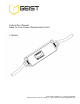
Specifications Overview The L Series products are In-Line Power Monitoring Units intended for connection between an AC Mains circuit and a Power Distribution Unit (PDU). The In-Line Power Monitoring Units are designed to be powered by either a single phase or a three phase AC input circuit and have an outlet or output cord and connector body for connection to an external device (such as a PDU). The In-Line Power Monitoring Units are rated from 12 to 32 Amps depending on the unit’s configuration.
Detachable Power Supply Cords L Series In-Line Power Monitoring Units may optionally be configured with an AC Inlet for connection to AC Mains power. Use only detachable power supply cords of the appropriate size and type, as stated below, with the unit. Use only with light PVC sheathed flexible cords (according to IEC 60227) or ordinary tough rubber-sheathed flexible cords (according to IEC 60245) that terminate in an attachment plug meeting local/national code requirements.
Installation Instructions 1. 2. 3. 4. 5. Using appropriate hardware, mount In-Line Meter to rack Plug In-Line Meter into de-energized branch circuit receptacle1. Connect external device to the In-Line Meter’s output outlet or connector. Turn on branch circuit to energize the In-Line Meter. Power on external device. Guidelines If the In-Line Meter is installed in a cabinet the ambient temperature of the rack should be no greater than 45C.
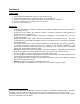
Optional Local Monitoring Power Meter The Geist PM-1 power meter is a low-power, high accuracy meter capable of measuring true RMS Current, Voltage, Power, and Power Factor. These values are individually shown on an easy to read, 4-digit LED Display, which continuously scrolls through the four different measured values. Each one of these displayed parameters is defined below. The Power Meter will automatically begin cycling through the displayed values when the In-Line Meter is connected to AC Mains power.
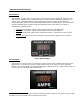
Three Circuit Current Meter The Geist CM-3 current meter is a low-power, high accuracy meter capable of measuring true RMS Current. The value of current per output circuit is shown on an easy to read, 4-digit LED Display. The display continuously scrolls through the three different measured values of output circuit current. The Current Meter will automatically begin to display value of output current when the In-Line Meter is connected to AC Mains power.
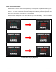
Optional Remote Monitoring Current Monitoring Meter Overview The Geist Current Monitoring Meter is a high accuracy meter capable of measuring true RMS current. The value of line current per input phase and output circuit current is shown on an easy to read, 4-digit LED Display.3 The display continuously scrolls through the different measured values. The Current Monitoring Meter also provides access to measurement data and control values through a web page, SNMP, or XML.
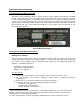
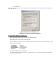
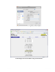
Click “OK” twice. You can now access the unit using your web browser at the permanent IP address of 192.168.123.123. Typical Network Card Settings for PC or Laptop to connect to default IP address First time setup (MacOS 10.5 and 10.6): Open System Preferences via the Dock or the Apple menu. Select “Network” under “Internet & Network.
MacOS X network settings for initial setup Connecting to the In-Line Meter using a web browser GM1045 Rev 2 10 Rev Date: 7/28/2014
LED Display Each In-Line Meter has a built-in 4-digit LED display mounted midway down the chassis. The display scrolls through the most recent current measurement (in amps) for each circuit, one at a time. It displays a circuit name, pauses, and then displays the measurement. Momentarily press the “Pause Scroll/IP Address Reset” button on the front of the In-Line Meter to pause the display on the current measurement.
Rebooting the Meter Should a Current Monitoring Meter with firmware version 1.36 or higher installed stop responding to network traffic, it is possible to restore functionality by rebooting the meter without removing power from the In-Line Meter it is enclosed in. To reboot the meter, press and hold the “Pause Scroll/IP Address Reset” button on the front on the In-Line Meter for 20 seconds. The screen will stop displaying scrolling power data in order to display the currently configured IP address.
The simplest way to get data from a Current Monitoring Meter into a script is via the XML page. Simply performing an HTTP GET (as a web browser does) on http:///data.xml will download the XML file. The following examples assume that the meter’s IP address is 192.168.123.123. Perl Example: using LWP::UserAgent; my $ip = "192.168.123.123"; my $browser = LWP::UserAgent->new; $browser->timeout(5); my $xmlFile = $browser->get("http://" . $ip . "/data.
3. Click the ‘MBrowser’ tab and expand the .iso tree down to geistmfg. 4. Select geistmfg and click the Start button. Getif should start requesting data from the unit via SNMP and display it in the large box at the bottom of the window.
Service/Tech Support Service and Maintenance No service or maintenance is required. Do not attempt to open the In-Line Meter or you may void the warranty. No serviceable parts inside. It is recommended that power be removed from the unit before installing or removing any equipment. More Technical Support http://www.geistglobal.com (800) 432-3219 Email: support@geistglobal.com Or contact your distributor.
Table of Figures Power Meter Display ................................................................................................................................................................. 6 Current Meter Display .............................................................................................................................................................. 6 Current Meter Display Sequence .................................................................................................
Revision History Revision 1.0 1.1 Date 6/17/2009 7/1/2009 1.2 6/29/2010 2.