
Specifications


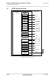
Table Of Contents
- Contents
- Tables
- Figures
- 1 Introduction
- 2 Interface Characteristics
- 2.1 Application Interface
- 2.2 RF Antenna Interface
- 2.3 Sample Application
- 3 Operating Characteristics
- 4 Mechanical Dimensions, Mounting and Packaging
- 5 Regulatory and Type Approval Information
- 6 Document Information
- 7 Appendix

Cinterion
®
BGS5 Hardware Interface Overview
1.2 BGS5 System Overview
10
BGS5_HID_v00.341 2013-09-23
Confidential / Preliminary
Page 10 of 41
1.2 BGS5 System Overview
Figure 1: BGS5 system overview
GPIO
interface
I2C
USB
ASC0 lines
ASC1/SPI
CONTROL
RTC
POWER
ANTENNA
(GSM/UMTS
quad band)
Module
SIM interface
(with SIM detection)
SIM card
Application
Power supply
Backup supply
Emergency reset
ON
Serial interface/
SPI interface
Serial modem
interface lines
I2C
3
4
4
5
2
1
1
1
2
USB
Antenna
1
PCM
Digital audio
(PCM)
4
Status LED
1
DAC (PWM) PWM
2
Fast
shutdown
Fast shutdown
1
1
ADC
ADC
1
COUNTER
Pulse counter
1
ASC0 lines
Serial modem
interface lines
4