
Specifications


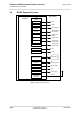
Table Of Contents
- Contents
- Tables
- Figures
- 1 Introduction
- 2 Interface Characteristics
- 2.1 Application Interface
- 2.2 RF Antenna Interface
- 2.3 Sample Application
- 3 Operating Characteristics
- 4 Mechanical Dimensions, Mounting and Packaging
- 5 Regulatory and Type Approval Information
- 6 Document Information
- 7 Appendix

Cinterion
®
BGS5 Hardware Interface Overview
Figures
41
BGS5_HID_v00.341 2013-09-23
Confidential / Preliminary
Page 6 of 41
Figures
Figure 1: BGS5 system overview.................................................................................. 10
Figure 2: USB circuit ..................................................................................................... 11
Figure 3: Serial interface ASC0..................................................................................... 13
Figure 4: Serial interface ASC1..................................................................................... 14
Figure 5: External UICC/SIM/USIM card holder circuit ................................................. 16
Figure 6: Schematic diagram of BGS5 sample application........................................... 23
Figure 7: BGS5– top and bottom view .......................................................................... 26
Figure 8: Dimensions of BGS5 (all dimensions in mm)................................................. 27
Figure 9: Reference equipment for Type Approval ....................................................... 32