
User Manual
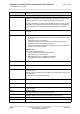
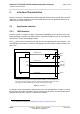
Table Of Contents
- Contents
- Tables
- Figures
- 1 Introduction
- 2 Interface Characteristics
- 2.1 Application Interface
- 2.2 RF Antenna Interface
- 2.3 Sample Application
- 3 Operating Characteristics
- 4 Mechanical Dimensions, Mounting and Packaging
- 5 Regulatory and Type Approval Information
- 6 Document Information
- 7 Appendix

Cinterion
®
ELS31-V/ELS51-V Hardware Interface Overview
2 Interface Characteristics
17
ELS31-V_ELS51-V_HIO_v00.502 2015-12-07
Confidential / Preliminary
Page 6 of 35
2 Interface Characteristics
ELS31-V / ELS51-V is equipped with an SMT application interface that connects to the external
application. The SMT application interface incorporates the various application interfaces as
well as the RF antenna interfaces.
2.1 Application Interface
2.1.1 USB Interface
ELS31-V / ELS51-V supports a USB 2.0 High Speed (480Mbit/s) device interface that is Full
Speed (12Mbit/s) compliant. The USB interface is primarily intended for use as command and
data interface and for downloading firmware.
The V
USB
line is used for cable detection only, this is to be supplied by the external device. The
USB circuitry in the ELS31-V / ELS51-V is designed to meet the USB 2.0 specification for self-
power.2.0”
1
.
Figure 2: USB circuit
To properly connect the module's USB interface to the external application, a USB 2.0 compat-
ible connector and cable or hardware design is required. Furthermore, the USB modem driver
distributed with ELS31-V / ELS51-V needs to be installed.
1. The specification is ready for download on http://www.usb.org/developers/docs/
VBUS
DP
DN
VREG (3V075)
BATT+
USB_DP
2)
lin. reg.
GND
Module
Detection only
VUSB_IN
USB part
1)
RING0
Host wakeup
1)
It is recommended to add EMI suppression filter (see section 2.1.3.1)
USB_DN
2)
2)
If the USB interface is operated in High Speed mode (480MHz), it is recommended to take
special care routing the data lines USB_DP and USB_DN. Application layout should in this
case implement a differential impedance of 90Ohm for proper signal integrity.
SMT